Camera kill switch not working?

Those kinds of chips don’t have any digital memory, and they don’t have a CPU on which to execute any kind of firmware.

1 Like

Love it. So impressed with the Librem 5. And thanks for the explanation!

Hope the issue is fixed for you soon, @ChriChri.

1 Like

does the killswitch indicator in phosh change in the top bar? If not this sounds like a hardware issue.

1 Like

OK, I don’t think there is any software component. You need to descend a few levels in your thinking.

However let’s say hypothetically there were a software component. Then the key question is whether it can be interfered with from the main CPU. If it’s an unalterable ASIC then it should be safe (albeit overkill) unless someone who has custody of your phone replaces the ASIC with a custom ASIC. If it’s alterable but not alterable from the CPU then if someone has custody of your phone then the malicious party could alter it. However as was pointed out above, if someone has custody of your phone then the switch can be made ineffective and replaced with a bypass wire (so it is always “on” even when the switch is in the “off” position).

All such attacks are also likely going to require a change to the operating system since, if you bother to operate the HKS, you are probably going to notice if it does nothing (particularly for the modem and the WiFi). A bypass wire by itself isn’t going to do the job and it would be quite a fiddly hardware hack so that the switch does something and the state of the switch is detectable by the operating system but the switch doesn’t actually kill the modem or WiFi.

The hardcore concern that is addressed by the HKSs is a remote software compromise of the operating system (which based on my experience is certainly still a possibility i.e. there are enough pwning exploits being discovered to think that there are still some more to be discovered - but that is an inherently uncertain statement).

Of course the HKSs for the modem and WiFi are also just good for reducing RF surveillance.

If you lose custody of your phone then there are many many possible attacks. So the primary goal is if you lose custody of your phone, know about it i.e. you don’t want someone to have custody of your phone without your knowing about it, then have that malicious party interfere with your phone, then return it without your ever knowing about any of this.

If the realistic threats that you face are severe enough then you should be using some of your nail polish to defend against generic hardware interference.

1 Like

O.k. - got some screwdrivers :). What should I look for?

Is there a written tutorial how to take the Librem5 apart to have a look at the board/switch?

Well, o.k. there’s a blog post not mentioned in docs.puri.sm.

When I removed the frame I found the little ‘pin’ marked in the picture lying on the pcb:

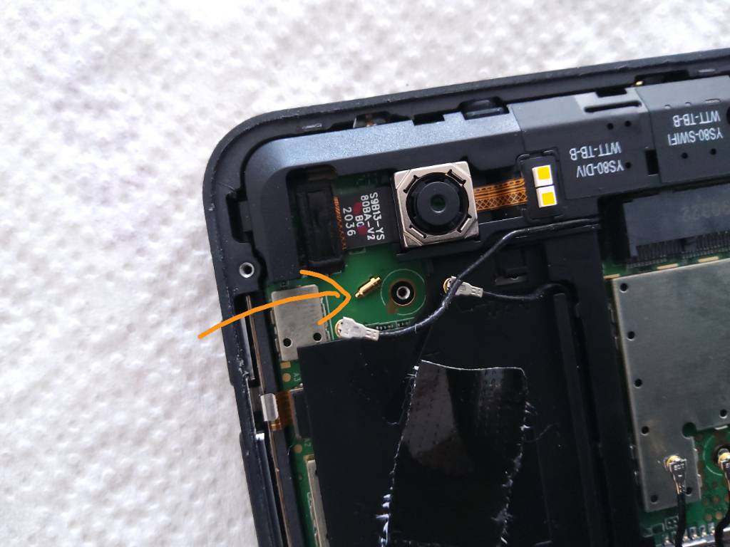
Any idea where that belongs? It hasn’t been fixed or connected anywhere, it was rolling on the pcb.

I got this far that I can see the switches.

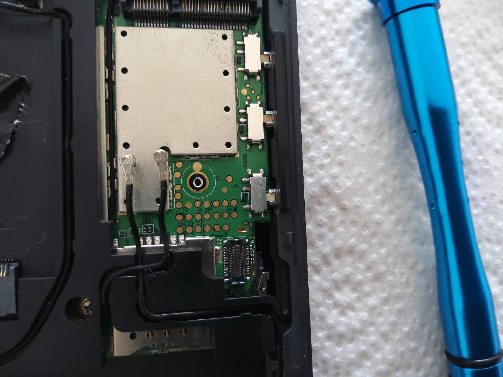
Any chance I can take a measure of the camera switch already on this side of the pcb? Would I break something if I’d use a common multimeter to test whether the switches pins do have connection?

You should be fine using a standard multimeter but you may want to remove the battery so that there is less chance of accidentally shorting a power rail to something that can’t handle that. If your multimeter has a continuity test mode you might be able to just check continuity between each pin of the switch and the flip the switch and check again. Without a continuity mode, you can instead use a resistance mode and check the resistance between the pins. If the pins are not connected at all, the multimeter will likely show something that looks like OL (for overload) but if there is a path between those two pins somewhere else on the board, the multimeter will show the resistance of that path. If the pins are connected, the resistance should be very low (potentially less than one Ohm). On my Chestnut L5 the middle pin is connected to the upper pin when the switch is in the upper position and to the lower pin when the switch is in the lower position. Based on your description, it seems that the middle pin on your switch may always be connected to the upper pin.

Be very careful though, even with the battery removed, there may still be capacitors on the board that hold a charge and could be shorted to something causing damage.

That loose pin in your phone is a bad sign though I am not sure where it might have come from.

2 Likes

The loose pin almost looks like a pogo pin. Did you pick it up at all? Is there a spring-loaded part? Maybe it fell off of the test equipment at the factory and fell into your phone.

@dcz, @guido.gunther

Any comments, additions, hints, warnings before I proceed?

I think you know about it as least as much as I do.

I would not use the continuity tester at all since the Voltage of the continuity tester on some multimeters can provide up to 9V that’s quite a lot for chips that are designed to handle 3.3V or below.
Try measuring the Voltage between the 3 pins of the switches while the Phone is switched on an then see if something changes between the Pins depending on the position of the switch.
But that’s just my option.

I do hope you know more than me :). Otherwise both of us do not know much about the hardware of the phone.

Good point. I really do not know how my multimeter does measure continuity or resistance.

I’d really need some competent guidance here by someone who knows how to diagnose the problem.

@dos, @guido.gunther any chance someone could give me instructions?

So you are determined that you are not going to contact Purism support?

1 Like

I can confirm that I studied the schematics and that kill switches really do switching on the hardware level which is not programmable. Some signal paths from them to actual power cut are more complex than others but it is quite complex task to distribute power without higher lost. So the power is distributed mostly on variable battery level 3.4 to 4.3 V and converted to required voltages in place of its use. There is wired/diodes/resistors logic to combine switches together for GPS switch off and rescue boot combination function. I am not sure if this passive logic does not draw more power than some advanced LVTTL chip. As for the components I can imagine some scenarios when some components can be powered by some I/O pin which is not cut. But most of connections to i.MX8M goes through level shifters so even that possibility is eliminated and I consider driving mobile baseband or WiFi through GPIO pin to the level that it can communicate as impossible. So even if some signal is omitted it cannot result in unsafe state.

What is a shame that at least components placement is not provided. Self-repair and experimenting with GPS antenna and other stuff is quite difficult without it and for these really paranoiac even possibility to check for tamper is much more difficult. It is even more shame that previous iterations was highlighted to provide X-rays scans etc… But world is not perfect… and I have knowledge at least to have some remote idea about amount of work to reach actual state… in i.mx1 days we have started from really chip level with zero lines of other code and with only self compiled GNU tools and serial bootstrap code and building own JTAG only later when already made Linux kernel and RTEMS system boot on the device.

1 Like

Why you is calling to @guido.gunther ? Guido asked you a question that you never answered him above.

1 Like

I suspect I found its origin. To me it looks the same as some pin that is positioned in the plastic frame:

This is what I decided to do to avoid the danger that might be my continuity tester to the Librem5. I made this little chart:

I measured the voltage between the middle pin of the switch and the other two pins. The table shows that in position 1 (up if the phone is upright) the voltage between the upper two pins is 0V and the voltage between the lower two pins 2.25V. If I move the switch to position 2 (down) the voltage between the upper two pins becomes 2.25V and the voltage between the lower two pins becomes 0V.

To me this looks like the switch is mechanically working and therefor probably not the cause of the misfunctioning of the camera kill switch.

I looked through the manual of my multimeter and the only information I found about the continuity tester is that the current used is smaller than 0.3mA - no information about the used voltage/signal. I guess I’ll have to measure it when I’ll have another multimeter around…

1 Like

Hi @ChriChri, I tend to agree with you the switch seems to be behaving as expected. And with your measurements, that also suggests that at least the outer 2 pins of the switch are connected to PCB otherwise you would not see the voltages behave like this.

1 Like

This.

So I reassembled my Librem5 and all I’ve got is this lousy pin.

:slight_smile:

1 Like