Case for Librem 5?

You could use this:

purism@pureos:~$ ~/guru/temp.sh
cpu-thermal: 33,00°C
gpu-thermal: 33,00°C
vpu-thermal: 33,00°C
bq25890-charger: 29,00°C
max170xx_battery: 31,10°C
purism@pureos:~$ cat ~/guru/temp.sh
#!/bin/sh

for i in /sys/class/thermal/thermal_zone? ; do echo -n `cat $i/type` ': ' ; cat $i/temp ; done | sed 's/ :/:/' | sed 's/: ../&,/' | sed 's/0$/°C/'
4 Likes

I made some more measurements and defined the model. It’s completely different from the original .stl, but I think it should fit pretty well (how easy it would be if Purism would just share the CAD models of the external of the phone).
It’s still 1 mm less wide than the phone. I suppose that a bit of stretch is needed in order to make it fit well the phone, but I don’t really know how much the material can be stretched. If someone has that data I can modify the model, otherwise someone has to waste some money to test it.
The final result is the following:


I look forward to listening to the comments

3 Likes

I have no idea, knowledge about 3-D printing and also no device for it. But, I’m willing to spent the money (even twice if necessary) and go to a commercial 3-D printing company.

What I would need for this (I do not even know what would be necessary):

  • the file to print
  • the exact material specification
  • the time it will cost (this defines the money to spent, I heard)
  • … anything else?

I.e. can someone please be so kind and give me the exact list of detailed information to hand it over to such company.

Thanks

2 Likes

well, it’s true that it looks like it !!!

Good remark, sometimes we miss the simplest ideas !

About material specification, I have used TPU with Multijet Fusion method and a raw finish (smooth or color was out of my budget for a test). The quality is very nice, and about the felling it gives the sensation of gripping as if you were holding a dry sponge.

The cost was around 45$ shipment included and the shipment was received around 15 days later (because I have not chosen the priority shipment).

Hello fiacco, do you mean this STL file ? It has been made by the community, last update was 9 months ago, so I assume it is Evergreen model (we have to check to be sure).

Anyway, I love your last model and help thank you so much

2 Likes

Oh, whoops, yes!
But I think it’s not up to date … or my phone is outdated.


I trust more my measures.
Here is the link to download the stl: https://send.vis.ee/download/3de5814d5ec13cde/#IjH9U0sh9Cn4oaYj87Wm4w
(I registered to the Purism git repo, but my account is awaiting approval from the administrator)
Let us know how it works

2 Likes

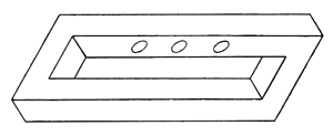
I think I found the original design here, note the holes for the 3 kill switches

:image

12 Likes

I’ll print it tomorrow at the library - cost is 0.70€ (<1$), so if it’s not perfect, it’s hardly any loss (I’ll donate it for the cause).

I can also do the infrared measurement of possible heat issues.

3 Likes

Thank you very much for your proposal. Please, just remember that if you print with a “not flexible” filament (like PLA, ABS, etc.), then it can be difficult to put the phone inside the case. If it happen, don’t worry and as a last resort, cut the case at few locations to make it more flexible.

Based on your job, I also trust you more ^^
The issue with the STL I show you was that it has no comment : we don’t know if this is an Evergreen model, nor if the measurements are correct.

Ay, that’s the plan. Works for a prototype. I was already planning on doing some minor surgery to get it in :smiley:

And this leads me to a new thought: rigid printing material is more available with hobby printers. It would be nice to have a version that solves the problem already by splitting the case in two. A prototype of this could be just a simple simple cut the length in two and have bit of thin overlap that can be fastened with tape from the back. A more sophisticated version…
A) the bottom could be a “drawer” mechanism that’s attached with rails on the sides or
B) there’s a hinge on the back bottom and it clips to place, or
C) a “giftbox” where the bottom goes inside the frame (overlapping sides), or
D) have only the sides wrap around the sides and on top of the screen edge (not the top or bottom, but they can go above edge obviously) so as to have the material flex a bit and grip the phone (the rigid will have bit of tolerance to do that but may need a couple of prototypes to perfect) [edit to add: this option is something I can test later by modifying the printed prototype]
… and probably a couple of other options.

For bumping (or protection from it) I’d have a bit of material in the corners to attach Sugru/Kintsuglue for a bit of elastic material to dissipate kinetic forces.
Something to think about, maybe.

The 1st company contacted for an offer replied: We can not do Multijet Fusion method (is this something exotic?) and we do not print in TPU due to poor demand of it.

remember that the case is 1 mm narrower than the phone. It wont work.

I don’t know either :grin:. All jokes aside that’s easy to fix, let’s consider it a prototype, I’m sure I’ll have to make some adjustment, I’ll add the comment then.

The case is not wide enough for the phone without flex? Well, that’s not good. Any chance you could quickly add 1-1,5mm there to enable rigid plastic use?

If the minor surgery includes sectioning it in half we’ll have the opportunity to check the matching of the profiles

Sure, tomorrow in the morning I’ll post a new version

Edit: CEST

1 Like

If it’s smaller on all three axis I’d have to cut it to 6-8 pieces and then it wouldn’t be very representative. I was thinking I may have cut it in half just to get it in, not because it wouldn’t fit. Adding a tiny bit all around, so it fit’s like a glove (+0.2-0.4mm all around it, or something like that) would be ideal.

No worries about the time. Preferably before 10 11 CEST would be good.

only widthwise, because it was so the starting file. I imagined that the stretch would allow for a better fit

It probably would. The prototype is good up to a point, to check other measurements - and maybe useful for other forks to develop the case.

Case with X,Y dimensions = phone + 0.2 mm
Front edge slightly reduced

1 Like

Ok, I’ve got a draft made. Needs a bit of polishing and if @fiacco (or anyone else) can and wants to make the fine tuning in time, I reserved time for tomorrow to do a better quality print (need the stl-file before 11.00 CEST or I have to print something else [or try next week sometime]). But let’s not get ahead of ourselves…

So, I printed using draft quality 0.4 (PLA in gray) which took about 1h50min with setting that i wasn’t very specific with.

It came out looking like an L5 but due to the design an L5 will not go into it.

So, I did some minor surgery, trying to do least damage. I opted to saw on the bottom sides, just inside the edge. The idea was that then the side would flex to let me slide the L5 in and the end would still flex and clip to place. It kinda did, as you can see. Wraps the phone around snugly and the edge raises just above the glass (even with my makeshift screen protector film on [note: it was for a One +1 but I just got a better one that is for a Vivo Y81, which has the correct shape and width and almost correct length that can be cut]).

And then the notes on what to work on:

  • As it went in, the drafts left side’s top edge split along the print. Possibly due to draft quality and fixable by glue. Adding a minor increase in the side wall thickness seems prudent (at least with this rigid PLA version - TPU may be ok). Something in the area of +0.5 perhaps [edit: for increased protection a full 1mm all around is of course better but at some point the gain will make using the buttons more difficult], which would only add to the width (back is supported flat against the L5’s back while top and bottom are shorter spans - only sides really flex).
  • The inside width was increased but it seems the inside length needs to be adjusted by +1,5mm [edit: added 0.5 to previous just in case]. You should be able to see that the bottom doesn’t quite reach the edge of the screen. In comparison, the top front edge looks perfect.
  • The bottom and side holes have good shape and position. However, I would reconsider making the bottom hole one wide hole. Splitting it into three would make the bottom a bit more sturdier (I’d use the same shape for the hole edges as now, not the sharp 90-degree corner “pillars” that the earlier draft had). Also, while printing, the middle sagged a little (for some reason the printer though it would not need to use temporary supports for the holes and it kinda did not [edit: meaning, the design could include temporary support pins/pillars that are meat to be cut off - other possibility being, that the printer/slicer will know if they are needed and ads them]).
  • Right side hole (power and volume) was easy enough to use. The bottom edge of the hole is very slightly nearer the volume rocker (compared to the top and power button), and that edge could be moved to make the hole longer, about 1mm [edit: decreased earlier by 0,5mm].
  • The left side hole is like the right, the bottom edge could be moved, about 1mm towards the bottom. But functionality-wise it has less meaning, as the HWK-switches are a bit different to use - you probably end up using fingernail or pen or something. The hole is a bit narrow and deep to use that kind of switches easily (at least with rigid material like PLA), but at the same time, widening would probably make the side too brittle - at least at the hole. I suggest not modifying this for now, as anyone can make the “quick-kill-hole” with a file or a knife, if they so choose.
  • The camera and flash holes are close and usable but a bit miss-aligned. I suggest moving camera hole 1,5mm towards left side and 0,5mm towards bottom. Flash hole 1mm towards left and 0,5mm towards bottom.
  • Top hole for the audio jack is slightly miss-aligned and seemed just a tiny bit too small (may have been the miss-alignment. Move center towards left side by 0,5mm and increase radius diameter by 0,5mm is my suggestion [edit: may not even be needed after re-alignment].

And as for making this usable for a rigid material version, how to get the L5 in and out, making the bottom similar to what I did now (sawing the bottom open) seems like a quick first version. I can either saw the new version again, or the needed cracksslits could be included in the design (but the I’d also add 0,5mm extra to the bottom thickness and additional thickness/edges of 0,5mm or so to the cracksslits, on the outside - just to make sure they do not become too much of weak points).


A different version alltogether: I also saw another type of protective rigid case (the orange picture) and it would also give (some) protection, while allowing easy removal and insertion of phone, and while being easy to get and cheap. Can this be a possible new “open ended” type? [edit: needs someone to cut the ends off in the design file]

[edit: By the way, looks awfully like the early prototype images of L5 with that grey :slight_smile: ]

5 Likes