Ok, I’ve got a draft made. Needs a bit of polishing and if @fiacco (or anyone else) can and wants to make the fine tuning in time, I reserved time for tomorrow to do a better quality print (need the stl-file before 11.00 CEST or I have to print something else [or try next week sometime]). But let’s not get ahead of ourselves…
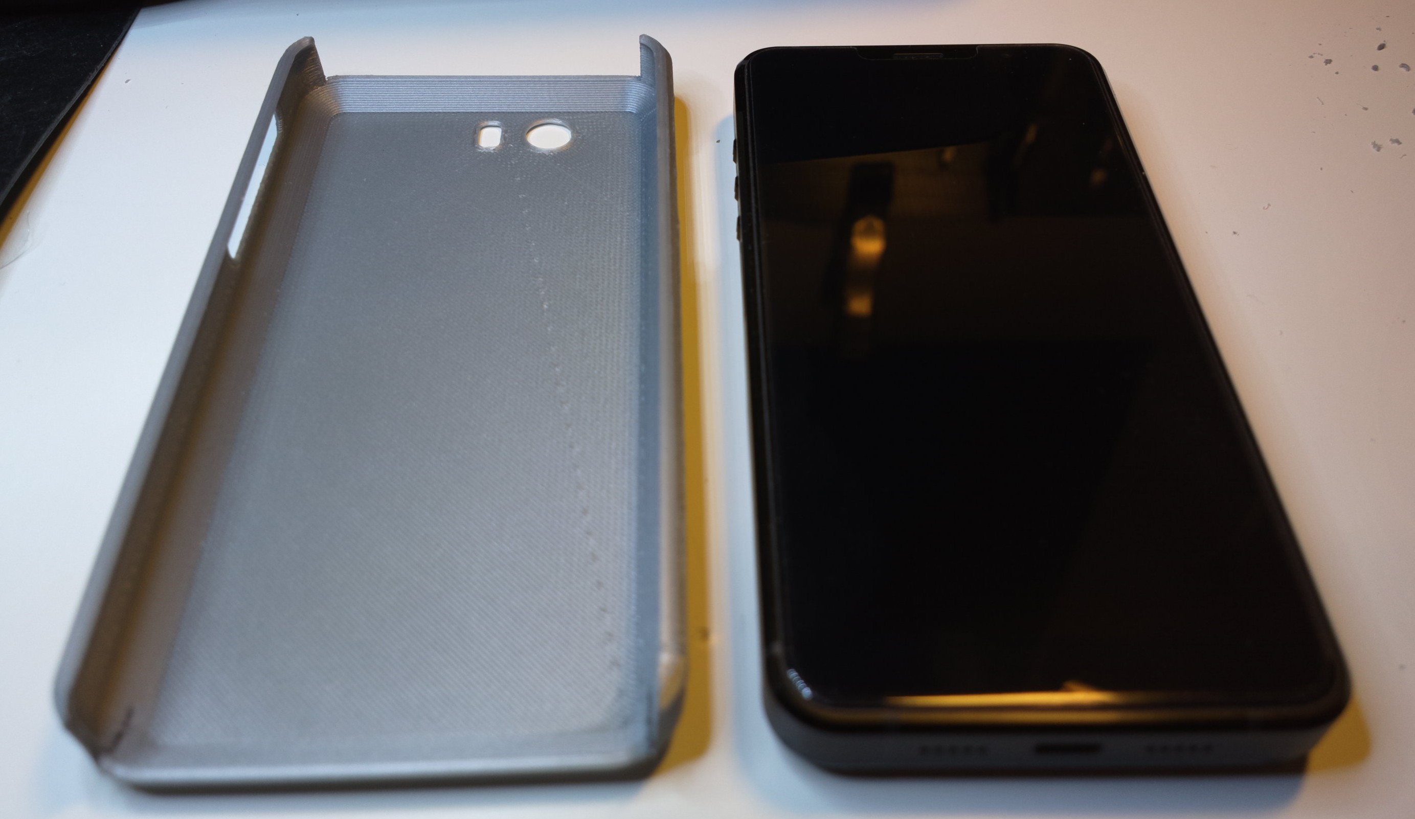
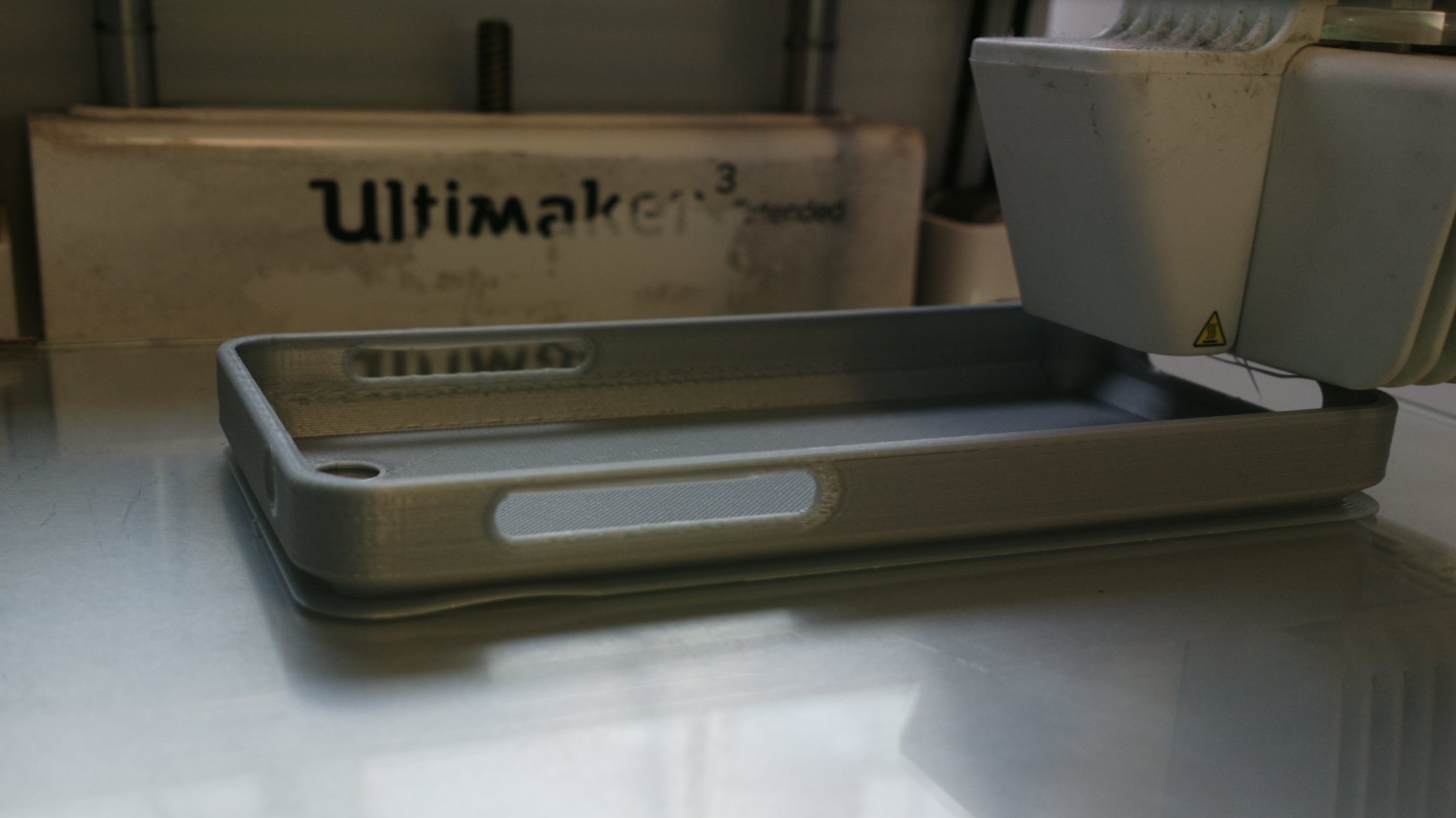
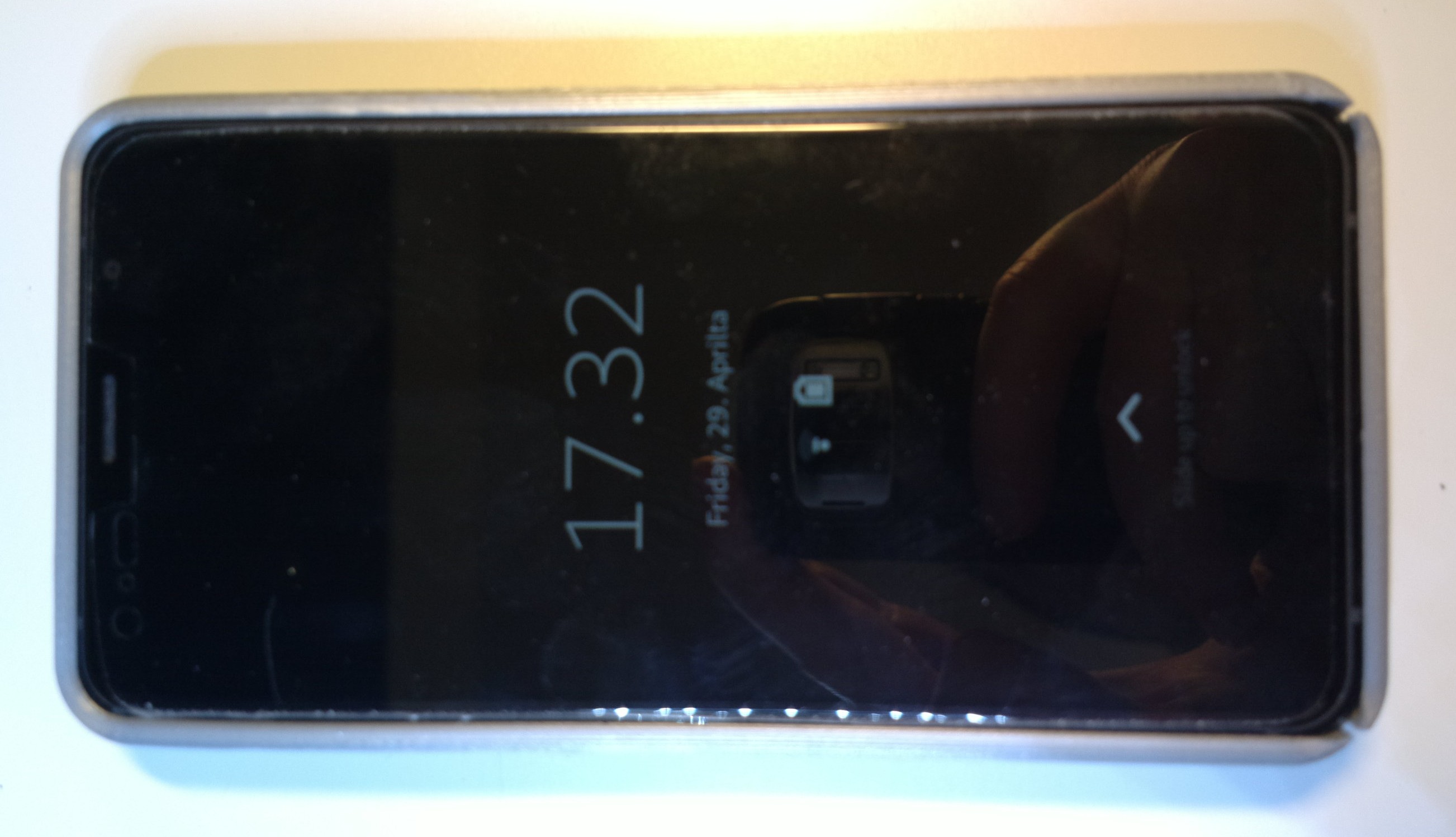
So, I printed using draft quality 0.4 (PLA in gray) which took about 1h50min with setting that i wasn’t very specific with.
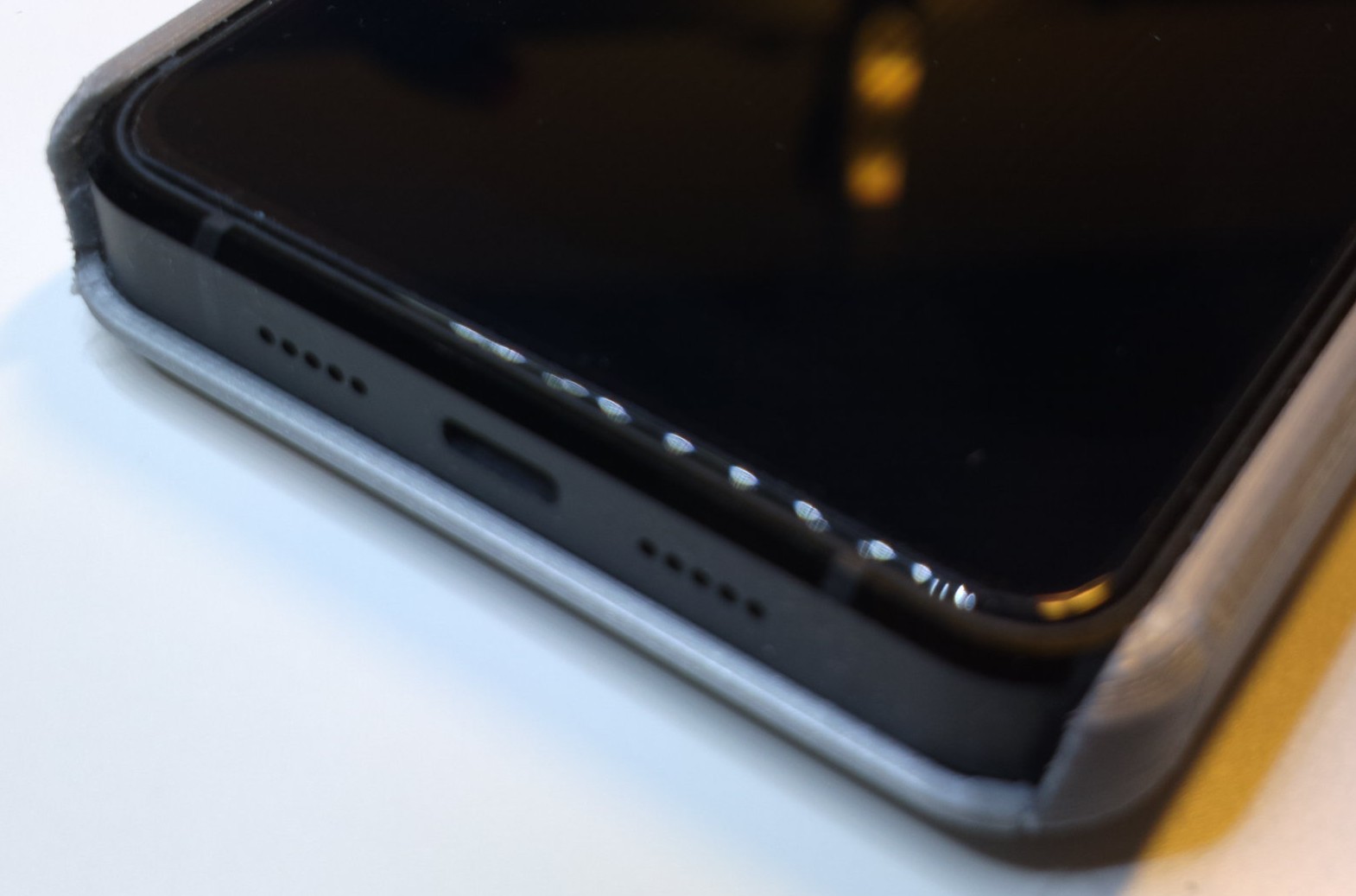
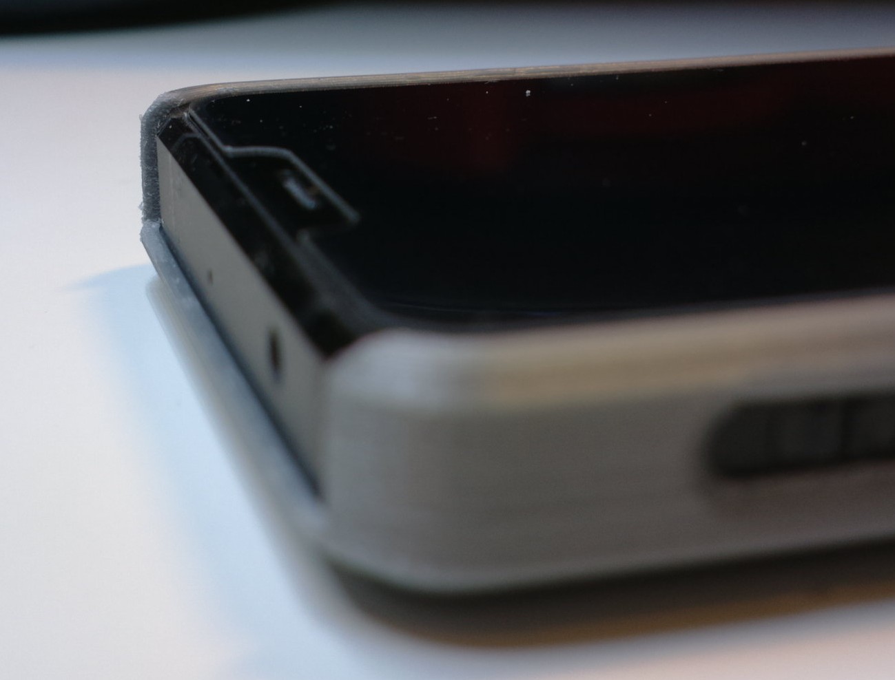
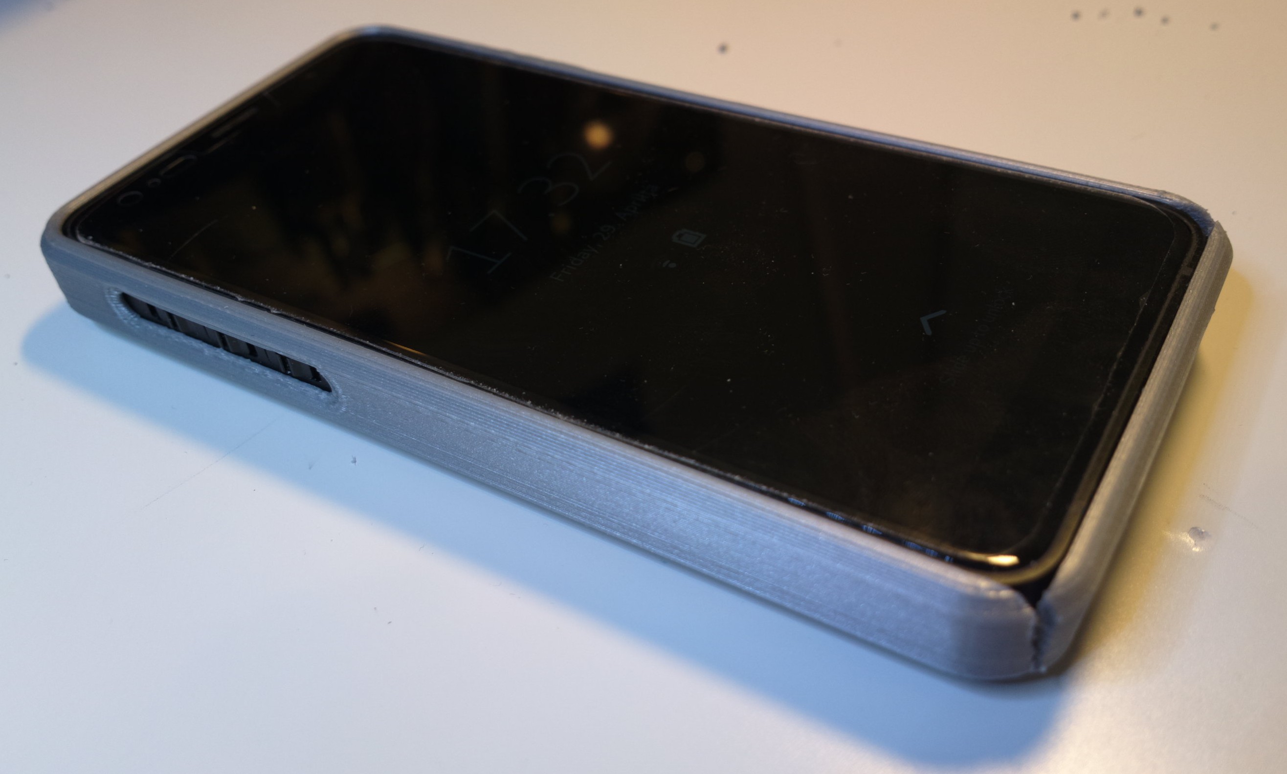
So, I did some minor surgery, trying to do least damage. I opted to saw on the bottom sides, just inside the edge. The idea was that then the side would flex to let me slide the L5 in and the end would still flex and clip to place. It kinda did, as you can see. Wraps the phone around snugly and the edge raises just above the glass (even with my makeshift screen protector film on [note: it was for a One +1 but I just got a better one that is for a Vivo Y81, which has the correct shape and width and almost correct length that can be cut]).
As it went in, the drafts left side’s top edge split along the print. Possibly due to draft quality and fixable by glue. Adding a minor increase in the side wall thickness seems prudent (at least with this rigid PLA version - TPU may be ok). Something in the area of +0.5 perhaps [edit: for increased protection a full 1mm all around is of course better but at some point the gain will make using the buttons more difficult], which would only add to the width (back is supported flat against the L5’s back while top and bottom are shorter spans - only sides really flex).
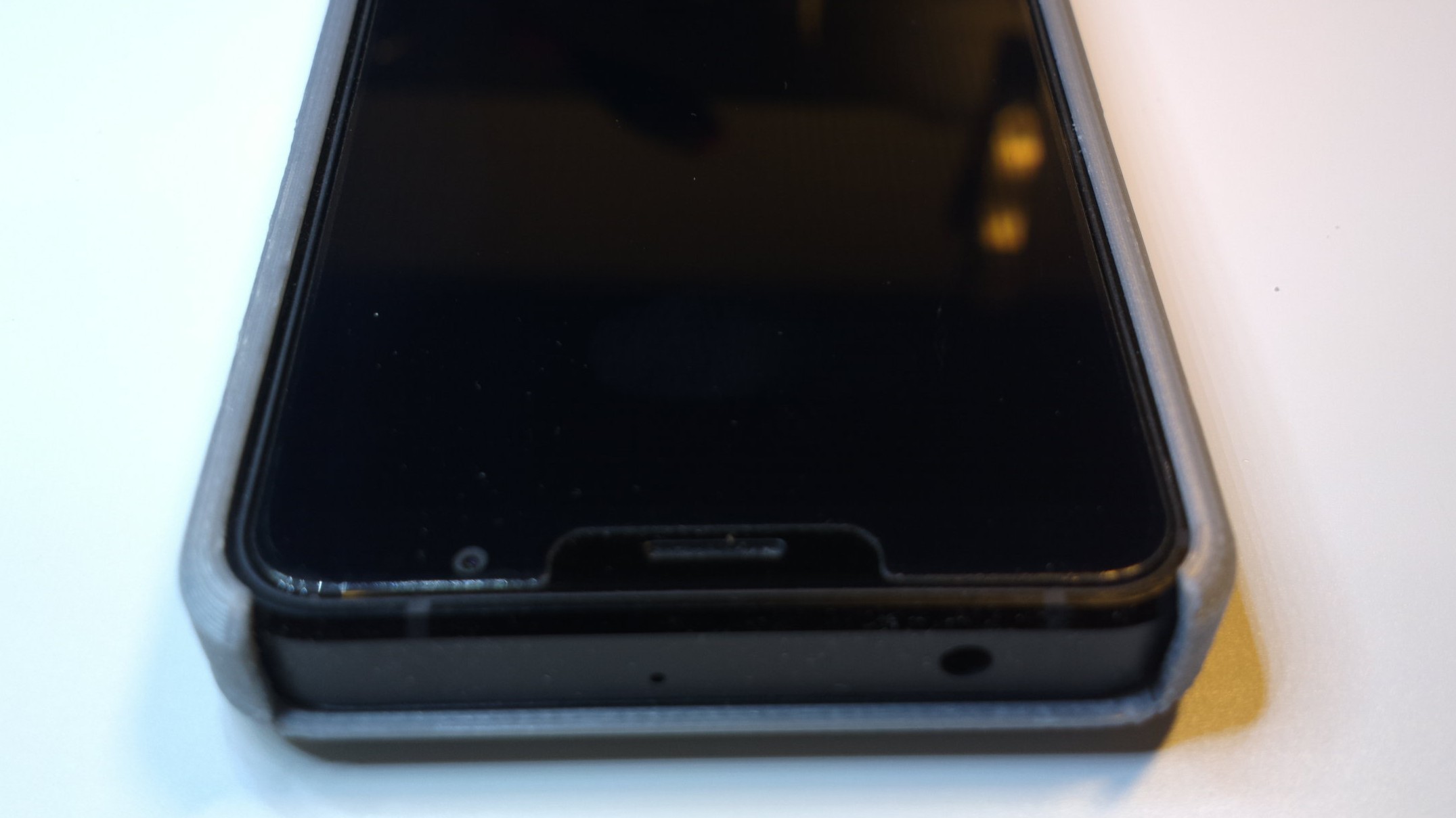
The inside width was increased but it seems the inside length needs to be adjusted by +1,5mm [edit: added 0.5 to previous just in case]. You should be able to see that the bottom doesn’t quite reach the edge of the screen. In comparison, the top front edge looks perfect.
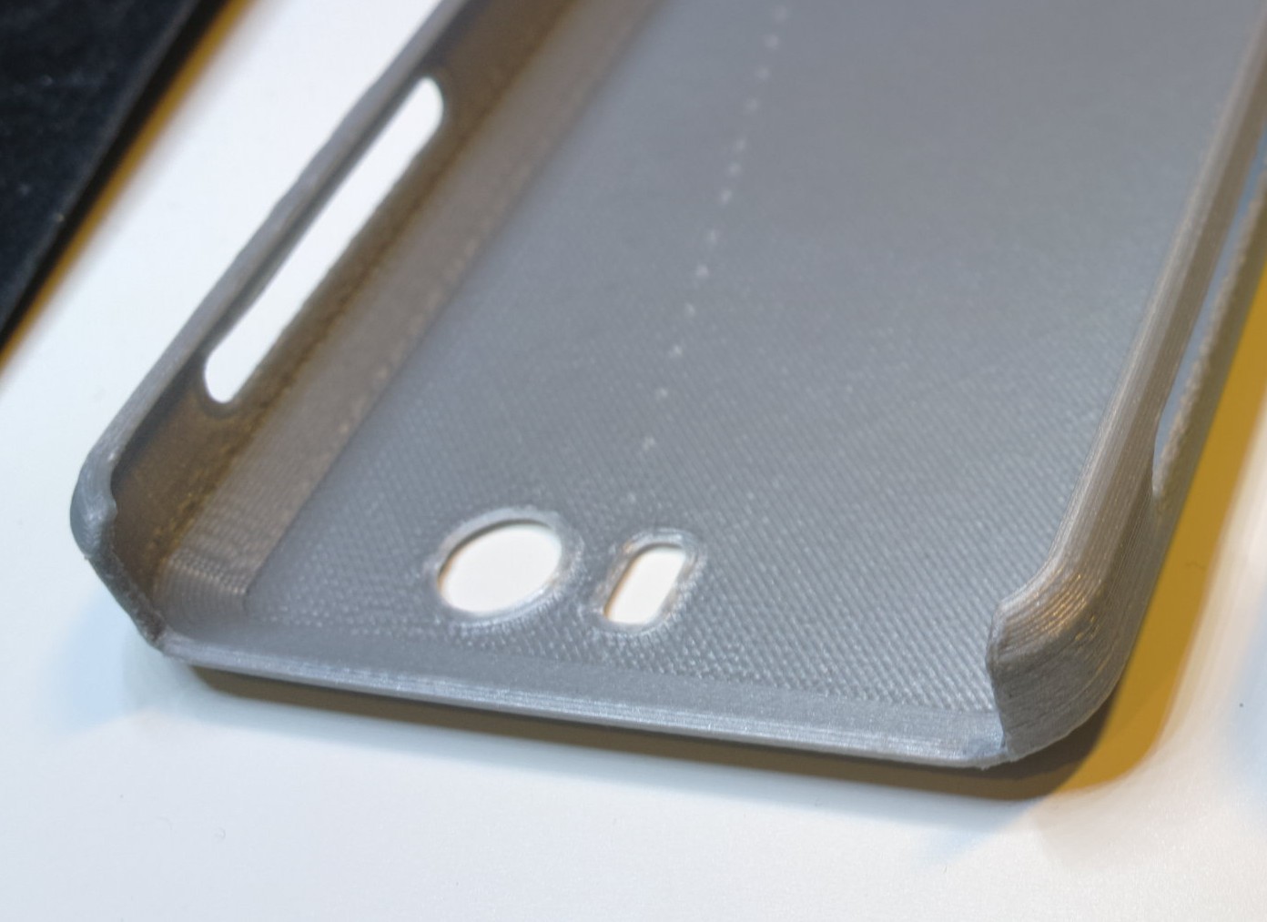
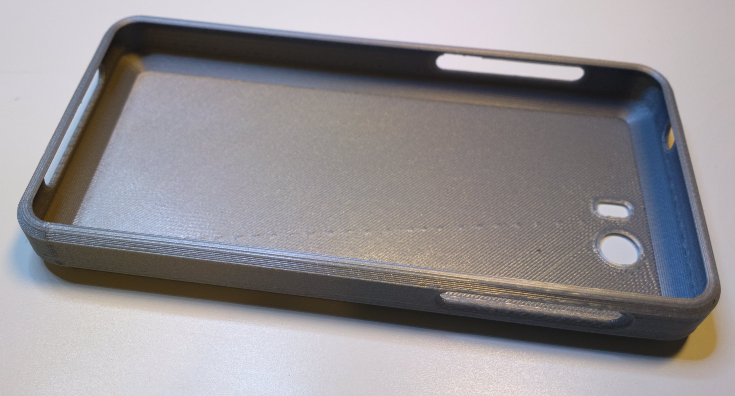
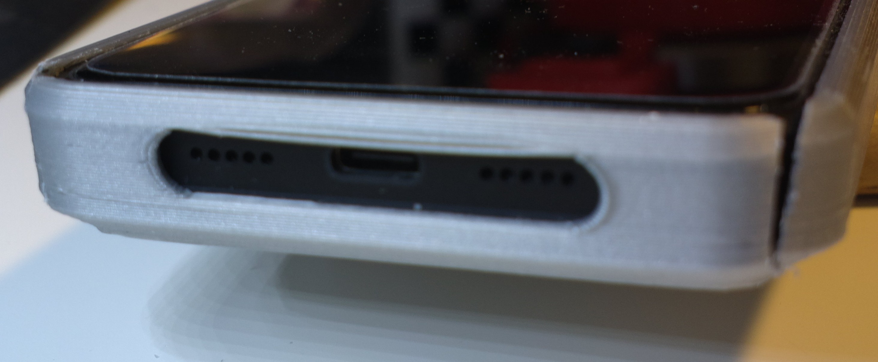
The bottom and side holes have good shape and position. However, I would reconsider making the bottom hole one wide hole. Splitting it into three would make the bottom a bit more sturdier (I’d use the same shape for the hole edges as now, not the sharp 90-degree corner “pillars” that the earlier draft had). Also, while printing, the middle sagged a little (for some reason the printer though it would not need to use temporary supports for the holes and it kinda did not [edit: meaning, the design could include temporary support pins/pillars that are meat to be cut off - other possibility being, that the printer/slicer will know if they are needed and ads them]).
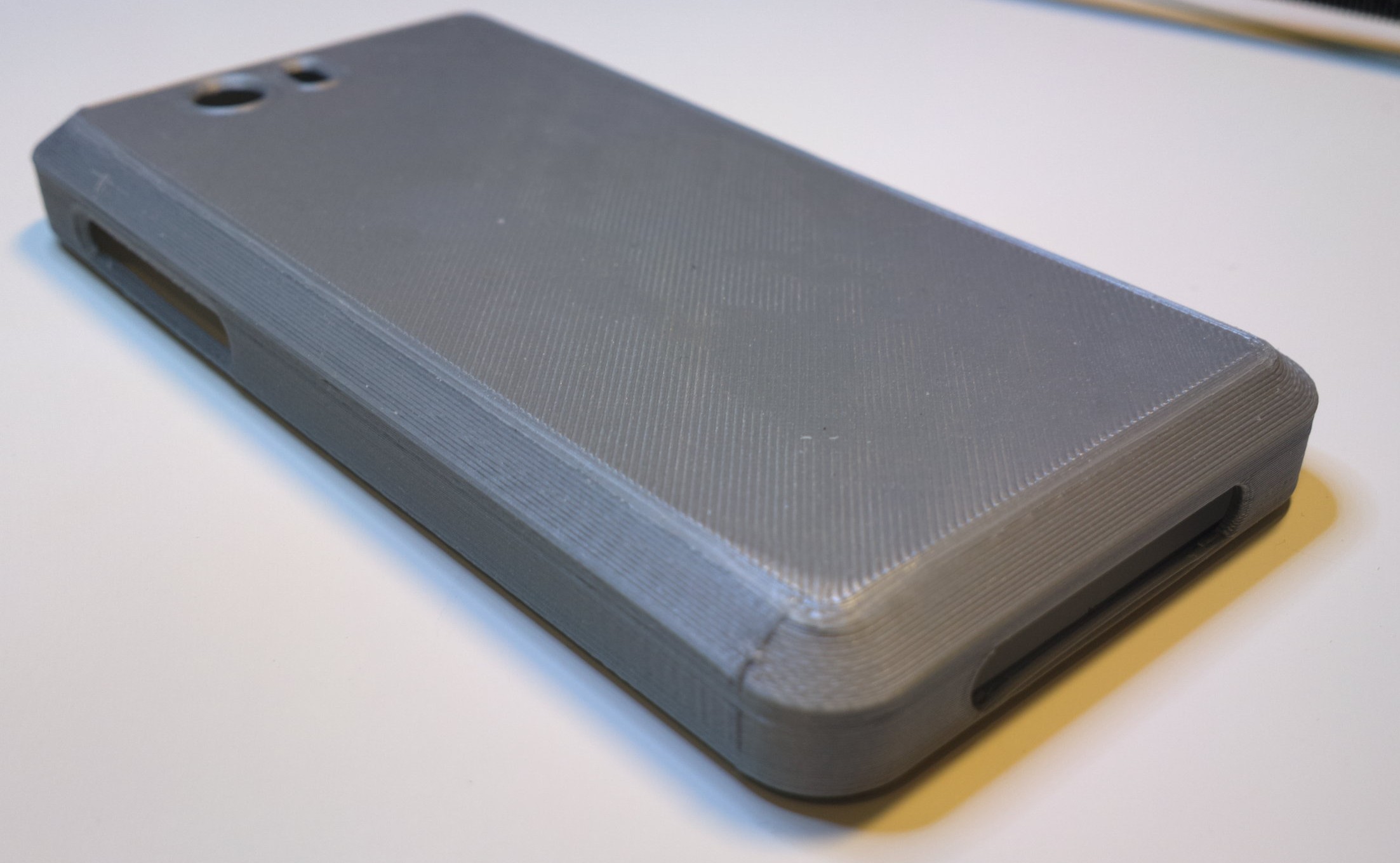
Right side hole (power and volume) was easy enough to use. The bottom edge of the hole is very slightly nearer the volume rocker (compared to the top and power button), and that edge could be moved to make the hole longer, about 1mm [edit: decreased earlier by 0,5mm].
The left side hole is like the right, the bottom edge could be moved, about 1mm towards the bottom. But functionality-wise it has less meaning, as the HWK-switches are a bit different to use - you probably end up using fingernail or pen or something. The hole is a bit narrow and deep to use that kind of switches easily (at least with rigid material like PLA), but at the same time, widening would probably make the side too brittle - at least at the hole. I suggest not modifying this for now, as anyone can make the “quick-kill-hole” with a file or a knife, if they so choose.
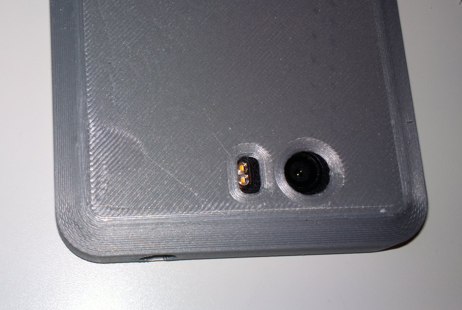
The camera and flash holes are close and usable but a bit miss-aligned. I suggest moving camera hole 1,5mm towards left side and 0,5mm towards bottom. Flash hole 1mm towards left and 0,5mm towards bottom.
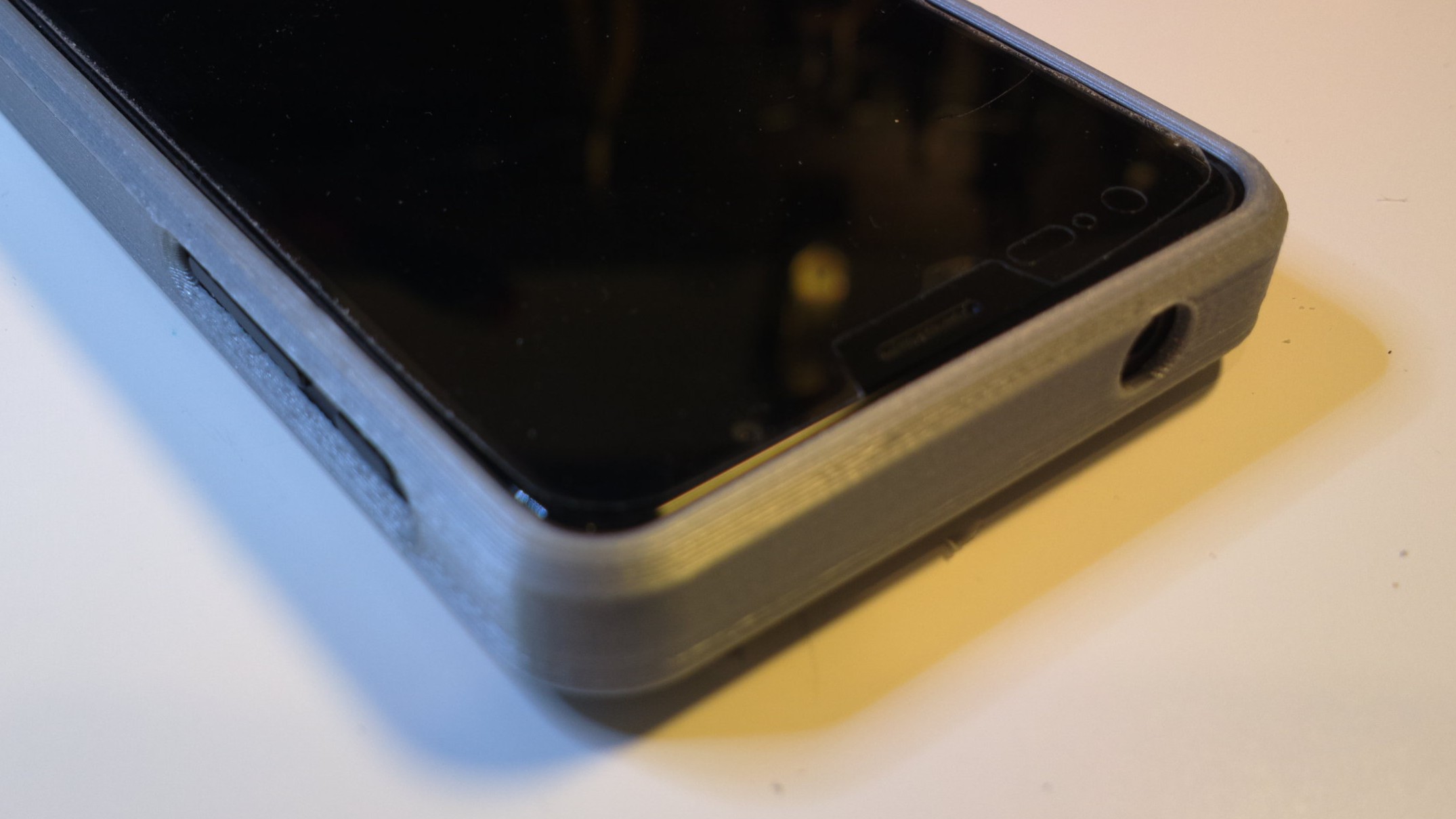
Top hole for the audio jack is slightly miss-aligned and seemed just a tiny bit too small (may have been the miss-alignment. Move center towards left side by 0,5mm and increase radius diameter by 0,5mm is my suggestion [edit: may not even be needed after re-alignment].
And as for making this usable for a rigid material version, how to get the L5 in and out, making the bottom similar to what I did now (sawing the bottom open) seems like a quick first version. I can either saw the new version again, or the needed cracksslits could be included in the design (but the I’d also add 0,5mm extra to the bottom thickness and additional thickness/edges of 0,5mm or so to the cracksslits, on the outside - just to make sure they do not become too much of weak points).
A different version alltogether: I also saw another type of protective rigid case (the orange picture) and it would also give (some) protection, while allowing easy removal and insertion of phone, and while being easy to get and cheap. Can this be a possible new “open ended” type? [edit: needs someone to cut the ends off in the design file]
For the killswitches, would it be acceptable to widen the portions of that hole only around the killswitches? Such that the long hole has “bumps” above and below the switches so you can fit your finger in there more easily. Does that make sense? Or are the switches to close together for that?
I don’t think that would make difference. Yes, they are close together and meaningful bumps would weaken the case at that point, as I tried to point out. It’s about how thick your fingertips are and how often you use them [switches] - some will be fine with how the hole is now.
Hello, this is not so exotic, if I understood well it is a HP technology (patent ?) allowing fine-grained materials that can do ultra-thin layers (so you shall not see them).
Its application is mainly a “final prototype” product or small series before injection molding for instance.
A few 3D printers service propose this technology.
Thanks, excellent! I’m going to go for 0.14 printing tomorrow, in black. Should look nice.
About the splits though: you have them (if Slic3r shows them correctly) at the corners towards center line at 45 degree angle. I think it might work better to have them aimed along the top inner edge. Possibly something to test later.
Also, I’m, pretty sure they need to be longer (10-30mm possibly), but I’ll have to test that out and estimate it with the new thickness and all - minor surgery again. They need to allow enough bend to insert L5 but be rigid enough to keep it tight. We’ll see.
Oh, and I had time to do a little rapid development with a saw and minor surgery with a crafts knife. Patient is… alive!
I turned the grey prototype to the orange v.2 type case. I sawed off the ends (leaving the corners and back edges to top and bottom) and now the sides grip the phone nicely (very snug, well designed - thanks againg @fiacco!), all while allowing the rigid material to flex enough for a MUCH more convenient insertion/removal. First impression is that it might work well and this model will benefit from the increase in thickness.
[edit to add: one more benefit of the v.2: it would be simple to attach a wallet/book type (faux)leather wrap to a phone with that holding it - if anyone likes that sort of cases… could probably find a suitably sized wallet/book case and swap the holder part]
Straight splits attached, you can choose. I was pretty undecided, but the 45° version looks nicer so …
It’s worth noting that +1.5 mm on the length is a huge change, I couldn’t be off by that much, I think it will be pretty slack now.
The open shell looks nice, but not very protective. I’m for the rubber all around, according to @prog-amateur idea
Send allows a maximum of 20 downloads, maybe already reached? Do you know a better file transfer solution?
Edit: just checked, still 17 remaining, must be something else
The length is probably 0,7-1,0mm short but the rigid is so snug that the extra 0,5 is no problem. This is probably a thing that needs experimenting with that TPU/rubber printing too, to get it just right. The rough draft version may also have had some heat deformity or rough surface to skew measurements. For that extra space, I can always insert a piece of fabric or something, which will act as cushion, if it comes to that. I’m hoping the next prototype tomorrow will tell more. [edit: it may take me until the night or until Sunday to update, not sure how it goes]
Ay, there is a tradeoff - particularly with rigid material - between protection and convenience on those designs. Maybe someone will find a third alternative, or fourth. TPU/rubbes has its benefits, but I’d really like a hybrid, that has a rigid body with bumber corners…
I also think your 1st release is the best for flexible material like TPU.
I was thinking about something… what about REAL silicone ?
I mean, we have a case shape, based on it, we could make a mask / mold that opens and closes and that we grease to avoid that the silicone that we would pour through a hole does not adhere to the mold?
What do you think, is it realistic ?
I think TPU will benefit from the changes too, to have everything well in place (just remember to remove the slits for that version). On the other hand, I’m also pretty sure there are some minorfixes needed after the first prototype too (even if it’s already usable).
I had the mold idea too but not the skill. Someone could also print a mold directly (invert the model in a block, i quess, and add holes to push material in). But standard latex won’t last long - you’d need to research something better (that’s not very hot, as that would warp a printed mold).
Nothing:
“Hmm. We’re having trouble finding that site.
We can’t connect to the server at eottzyhzdhyvhj22oueqmmtrvnblfaykhwmdnm4xm2yvdb5aq22e2qyd.onion”
Not the “DIY” in my opinion.
I’ve found this website: https://www.protolabs.com/ they offer a huge range of materials and technologies. I think they could do prototypes as well as small series, they have facilities in the United States and Europe. I will ask for an offer as soon as I have a good model for an elastomeric case.
Absolutely. BTW, since you removed the top from the first prototype could you please check the matching of the internal profile with the phone? Just by placing the little piece on the side of the phone ans see if there are clearances …


 ]
]