Antenna design for mobile GPS is much more complex than the space available in this forum allows for explanation (and I don’t regard myself as an expert in this field). The antenna used in the GPS module is most probably a Planar Inverted-F antenna (PIFA), although other variations are possible.
What I tried to explain was the effect of a bad antenna connection. The differences between the receiving path, direct - indirect, is exaggerated and partly misleading …
For reflection of the back plane or earth it’s best to assume that both direct and indirect path are passing through the antenna. The next picture explains the amplifying effect of reflector at 1/2 wavelength.
The dotted line is the reflected wave, arriving at the antenna in the same phase as the direct signal. As such the reflector improves the GPS signal, hopefully just enough to increase signal/noise ratio above the threshold level.
To answer your question: the reflector is best placed on an integral number of half wavelengths.
The use of many baking plates leads ultimo to a parabolic reflector. It’s best to put the L5 in the focus-point
What I understand from this and other explanations in this tread and from own experiments, it seems to me that in the L5 something around the GNSS chip/antenna/earthing is bad or let’s say not optimal constructed, i.e. it is a hardware issue. While any software issue can relatively easy be fixed by installing an updated version, how Purism could address such a hardware issue?
And, why they didn’t detected this before in own tests, or in the versions before Evergreen?
It looks like it can hold the fix when putting the L5 in less optimal positions. When I then stop the command with CTRL-C, but keep the phone in the less optimal position, the L5 cannot establish a 3D fix again. So, I think that somehow the L5 can sometimes maintain a 3D fix in a location where it cannot freshly establish a 3D fix.
Are there any L5 owners that can always easily get and maintain a 3D fix when outside, without applying special configurations?
As I mentioned before, antenna problems are per definition very complex. Taken into account that GPS signals are relatively weak, variations in mm of antenna placing can already have big effects. Especial the connection between antenna and module is critical. Even if the connection is soldered, the connection may deteriorate due to e.g. vibration during transport. Example: a hairline crack in the connection induces a wave-reflection point, resulting in a severe reduction of signal. If this, for the naked eye invisible, crack is on the right place then the result is a better reception… (see: Standing wave theory)
If the percentage of bad GPS receiving L5’s is high, I strongly advice a re-engineering of the GPS antenna construction. A robust design is needed for large quantity production.
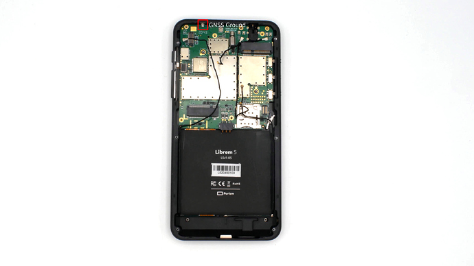
Purism confirms antenna possible problems on some pieces. It has been already mentioned in this thread and there is somewhere suggestion how to try fix ground connection between metal frame and board. I have not found time and courage to disassemble my Librem 5 and try to fix that. But I try that when I have less duties at the university and company
There is fix heading to mainline which can probably lower some interference between SDIO and GNSS receiver. I am not sure/not checked yet, if it is already included in stable kernel 5.13.0-1-librem5. If you have while, you can check if switching WiFi off enhances SNR
arm64: dts: imx8mq-librem5: Limit the max sdio frequency
This is needed for the 1LV Cyress WiFi module to probe correctly.
It also helps improve GNSS sensitivity.
#Disable WiFi/Bluetooth
echo 0 | sudo tee /sys/class/leds/wifi_en/brightness
because you can not switch off all three HKS (which would shutdown the GNSS too). But the file /sys/class/leds/wifi_en/brightness does not exist in my OS Byzantium. Any idea?
But if you switch off mobile and WiFi off then interference from the sensors should be minimal. Cameras should be stopped (power down) as well when not used. So I think that test and comparison with modem and wifi on and off by switches should be enough.
a company doing such an excelent marketing should at least be able to design a hardware that can do gnss. otherwise i suspect they do bigger efforts in sales than in producing their products. while that is normal in todays usual companies i wouldnt expect that from an open source company
I regard this an unfair statement. Even with thorough design and testing of prototypes you still can be unlucky in exception cases. Still remember the “dead grip” of some Iphones. In production batches this type of incidental cases reveals itself in bigger samples. It can than be solved for next generations and manual repair in individual cases.
which is apple which for sure has the marketing problem i describe: much more effort is put into convincing people than developing the product. apple produced alot of failures that easily could have been avoided by putting more efforts in.
Are you willing to share the content of the mails you got back from Purism? This will help me to determine if I have to contact them as well or not. I prefer to keep the load of the Purism support as low as possible, so maybe if you share their replies, it will not be necessary for me to contact them.
i can tell the flow but can’t paste the text without senders permission. 11/25 i told them about the problem, 11/27 they answered which kind of debugging i did (while i pointed them to this thread where this question was already answered), 11/27 i answered what i did, 11/29 they asked for my script i used, 11/30 i answered i used cat /dev/gnss0 | awk '/G.GSV/{print $0}', 11/30 they told its forwarded to the dev and asked for the order number (which should be clear from my email adress already), 11/30 i send the number, 12/1 i asked what the devs say, 12/1 they asked me for patience, 12/13 they came up with a test flow that i already did (written here in the thread), 12/14 i told them so, 12/23 i asked for any updates, 12/25 they told ‘not yet’.
I have consulted Librem 5 design with Marek Peca, long term expert for satellite two way time synchronization and microelectronic and optronics systems designs and reserach. His modulators and receivers are used in space and CZ company Eltvor.cz/ works on new modems delivery to ESA now. Time modems use similar but more advanced TDM and correlation techniques as GNSS. He works at ESA on next satellites etc.
We have analyzed Librem 5 Evergreen schematics diagram. It is shame that components placement is not provided. But we moved forward a little anyway. There seems to be multiple alternatives how to assemble the board. Actual design and assembly clamps U20 BGA725L6 Low Noise GNSS Amplifier (LNA) input to the screw TS3 SC-M1.4. The resistor R256 and inductor L3 are shortcut. Rest of adaptation/resonator is not assembled. Location of the ANT3 ECT818000500 connector is not clean, visible or is under LNA shielding. I have not disassembled my Librem 5 yet, I wait for Purism confirmation about warranty in such case. It seems that signal is sourced from the TS3 screw which is connected to some antenna on the other board side. May be on heat spreader or somewhere??? Has somebody a photo?
Colleague considers problematic about 20 mm narrow path against the board (probably FR4 prepreg) to LNA which can cause significant signal loses. He considers as strange relatively high distance between antenna input (screw) and grounding point marked in Purism’s note. He suggest to add another connection between frame and PCB ground near to the screw path. The design of the line through screw is suspicious to me, how is controlled line impedance computed through that point? It can be source of many reflections probably.
He suggest to bring signal by coax to the LNA input. He thinks that he have some antennas to test that. I can imagine that building Librem 5 remix with external connector and bigger GNSS antenna can result in high quality positioning device. External antenna can be outside of car or boat then. Simple quarter-wave antenna for 1575.42 MHz (wavelength 0.19 m) should be around 48 mm. In the case of need and probably some funding, I can ask people who develop systems for antenna design simulations at our university or may it be some would provide input on base of their enthusiasm. In the fact Marek experiments with antennas design for satellites now.
The Librem 5 photo and components analysis by Marek Peca
Generally I understand that design in the constrained space is demanding, but there the seems to be some problem. I have never seen S/N above 27% of full scale on my Librem 5. Mostly around 10% which is miracle that STM TESEO-LIV3F even gets fix/lock sometimes. So all available design data should be provided to help with analysis and looking for solutions.
Most of your post is over my head (which is fine, I don’t pretend to design any electronics for a living, let alone specifically GNSS units) but maybe you should bring it to the attention of Purism or even get Purism directly in touch with your associate.
This is a fairly confusing way of quoting signal strength if you are actually just quoting the number that comes out of the GSV message.
OK, I really do not know what is expected GSV range and my adding percentage character is misleading. The Quote from the Teseo-LIV3 GNSS Module - Software manual:
SatxCN0 Decimal, 2 digits, from 00 till 99 Carrier to Noise Ratio for satellite x in dB,
So the maximal value which can be shown (full scale) is 99. Yes it is quite possible that such value cannot be reached and or can even mean signal level which can over-saturate receiver. But the Teseo-LIV3 manual specifies that it starts to compute position and attempt to reach position fix only when it is in sync with four satellites with S/N ratio above 20, i.e. 20 dB. Use of percentage is my mistake, but I was not looking into manual at that moment and considered 20 as percentage of whole scale to 99. Yes it is logarithmic…
Important is what are usual values S/N obtained on different Librem 5 pieces and what is expected range from Teseo-LIV3 designers. And I consider my typical read values about 20 or even less even for strongest satellites outdoor as really out of nominal expected range of the GNSS module designer.
I wait for response from Purism support and I have pointed them to this discussion. In the fact I did not plan to respond there until receive a reply. But Marek has gone through analysis further and attempted to locate components etc. so I have decided to pass his observations into public knowledge pool.