I have consulted Librem 5 design with Marek Peca, long term expert for satellite two way time synchronization and microelectronic and optronics systems designs and reserach. His modulators and receivers are used in space and CZ company Eltvor.cz/ works on new modems delivery to ESA now. Time modems use similar but more advanced TDM and correlation techniques as GNSS. He works at ESA on next satellites etc.
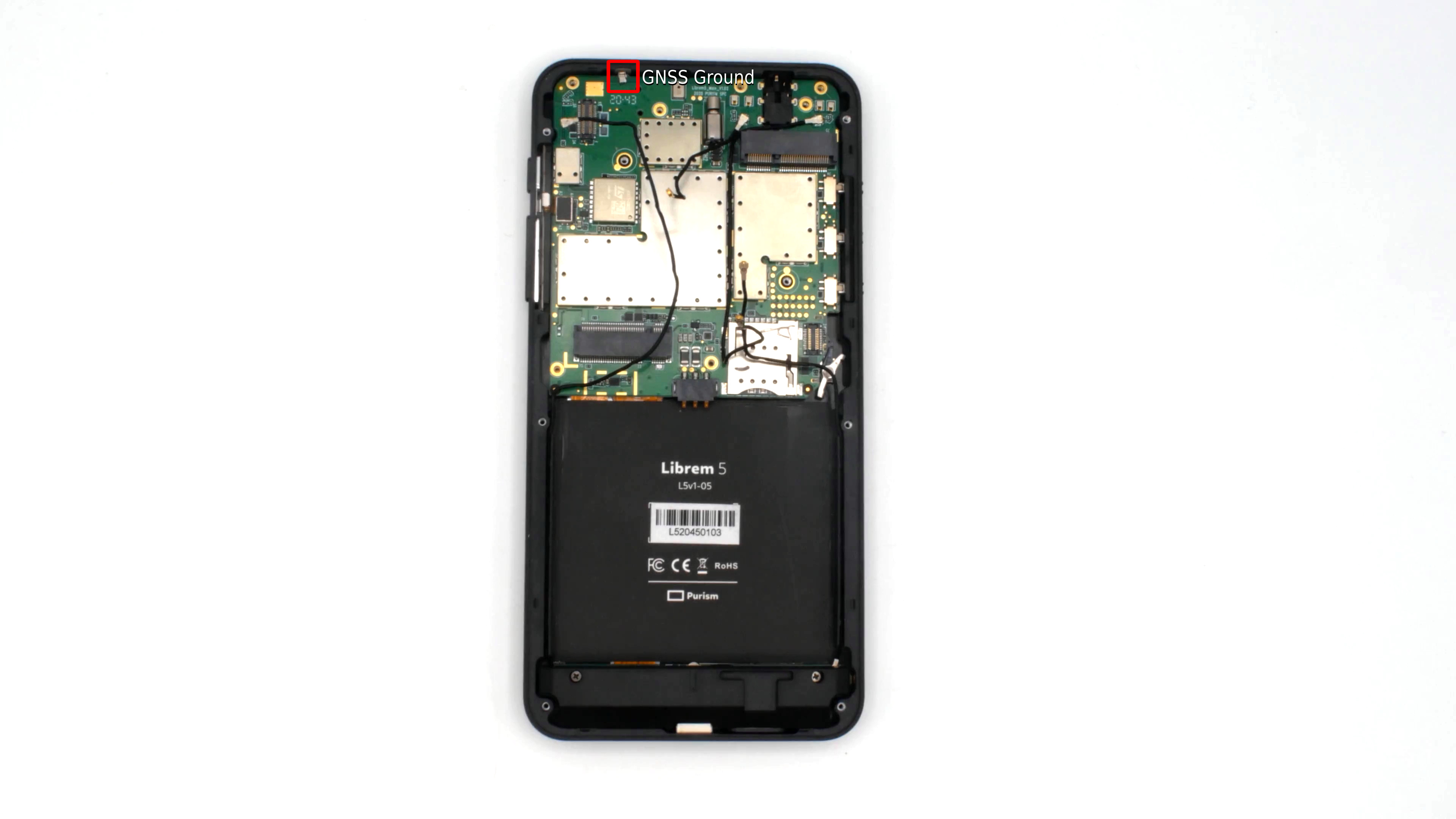
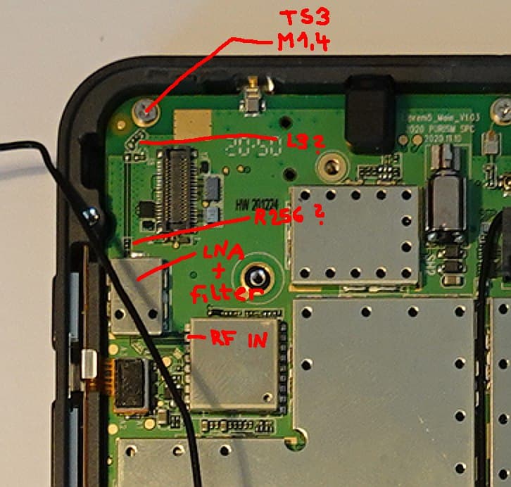
We have analyzed Librem 5 Evergreen schematics diagram. It is shame that components placement is not provided. But we moved forward a little anyway. There seems to be multiple alternatives how to assemble the board. Actual design and assembly clamps U20 BGA725L6 Low Noise GNSS Amplifier (LNA) input to the screw TS3 SC-M1.4. The resistor R256 and inductor L3 are shortcut. Rest of adaptation/resonator is not assembled. Location of the ANT3 ECT818000500 connector is not clean, visible or is under LNA shielding. I have not disassembled my Librem 5 yet, I wait for Purism confirmation about warranty in such case. It seems that signal is sourced from the TS3 screw which is connected to some antenna on the other board side. May be on heat spreader or somewhere??? Has somebody a photo?
Colleague considers problematic about 20 mm narrow path against the board (probably FR4 prepreg) to LNA which can cause significant signal loses. He considers as strange relatively high distance between antenna input (screw) and grounding point marked in Purism’s note. He suggest to add another connection between frame and PCB ground near to the screw path. The design of the line through screw is suspicious to me, how is controlled line impedance computed through that point? It can be source of many reflections probably.
He suggest to bring signal by coax to the LNA input. He thinks that he have some antennas to test that. I can imagine that building Librem 5 remix with external connector and bigger GNSS antenna can result in high quality positioning device. External antenna can be outside of car or boat then. Simple quarter-wave antenna for 1575.42 MHz (wavelength 0.19 m) should be around 48 mm. In the case of need and probably some funding, I can ask people who develop systems for antenna design simulations at our university or may it be some would provide input on base of their enthusiasm. In the fact Marek experiments with antennas design for satellites now.
The Librem 5 photo and components analysis by Marek Peca
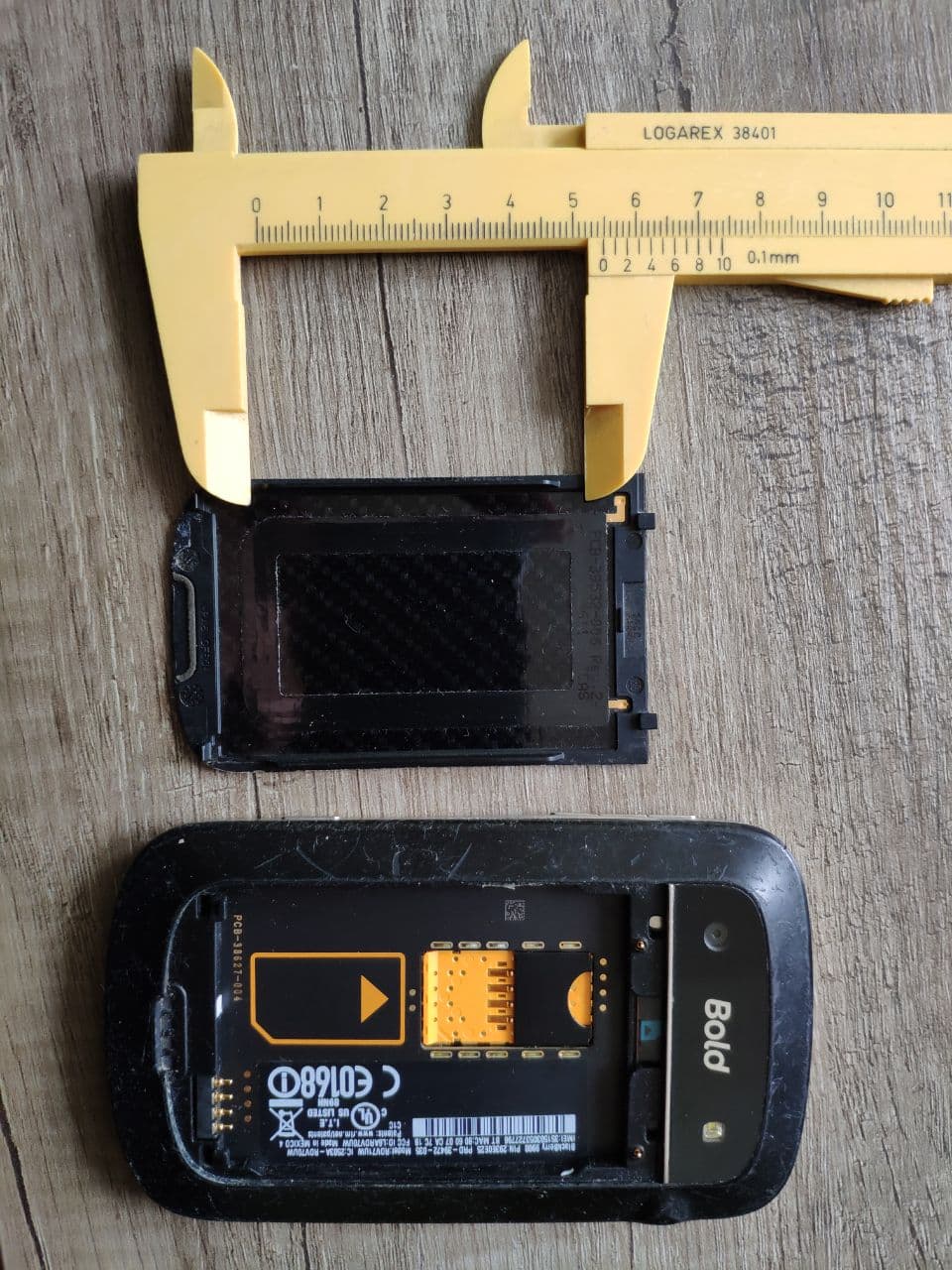
BlackBerry back cover GNSS antenna
Generally I understand that design in the constrained space is demanding, but there the seems to be some problem. I have never seen S/N above 27% of full scale on my Librem 5. Mostly around 10% which is miracle that STM TESEO-LIV3F even gets fix/lock sometimes. So all available design data should be provided to help with analysis and looking for solutions.