News regarding Librem5 on Chaos Communication Camp 2019

For a phone, range is important. 802.11ac only helps with the 5 Ghz band, so if you are beyond 2 walls, then you are probably not using 5 Ghz. It will be as if you are still on 802.11n. The 802.11ad speed is only if you are in the same room, and close by. A 802.11ad Wi-Fi card will include 802.11ax features, but it will be a while before it becomes available. 802.11ax adds Target Wake Time, which improves battery life. ax also improves the speed and reliability of 2.4 Ghz at longer distances in crowded channels, and requires WPA3 for better security.

3 Likes

Size 2230 for WiFi/BT and 3042 for cell.

I would love a 3042 M.2 915 MHz LoRa module. At lower data rates, they have great range. It would be nice if the hardware would support both VoIP (connect to a SIP server) and walkie-talkie (phone-to-phone, no infrastructure) use cases. Only 8 to 14 kbit/s is needed, depending on the codec. Some have built-in packet loss concealment.

4 Likes

Wow

@nicole.faerber is obviously amazingly knowledgeable.
Even though I would like to have the device already in my hands I am really happy I supported this project.
People like the folk in Purism are amazing.
Thank you guys

7 Likes

If someone ever asks me about the size of this thing I will simply say. This is not simply a phone. This is a full mini PC.

7 Likes

I never heard of anyone wanting a thinner smartphone. At least the Librem 5 will not have a camera bump. I would still use an add-on that made it thicker if it meant adding other cool features, such as wireless charging, NFC, e-ink notification area, or a larger or supplemental hot swappable battery.

2 Likes

I still not 100% sure which side is the front side. I also assume that the m.2 cards need to be on the side which would be open. But some phone get opened from the screen side. So if the case design is more like many iphones where 2 screws on the bottom secure the screen and after removing them the screen can be lifted up the board could be the other way around and would align with the day 16 video.
I think the advantage of such a design is that no inner frame is needed where all the board and the screen are fixed on where the back cover is lifted. So they might have chosen this design. Thought i consider replacing a battery on such a desing more complex as the display cables probable need to be remove an are kinda fragile. So for ease of battery replacement i would hope for back cover removal first and not screen first.

I made this with my guessing what the connectors are might for (assuming back cover removal first) . What do you think?

Edit:
I had another thought, which argues for a screen first opening. All renderings are showing the back cover as one part ( including the sides). But as all the buttons and jacks are kind of attached the case this would made it really hard to remove the back without also having lot of buttons an connectors to fiddle around. And thinking of this i haven’t seen a case design where the back is open when it is one part. Back opened phones have separate sides and a flat backplates most of the time i think. But i also think that the cover renders are the more uncertain information. So the rendering might miss a separation line, like its missing screws.

Edit2: other side
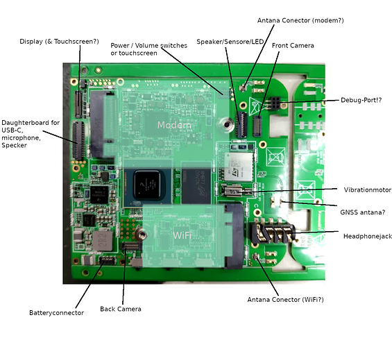
6 Likes

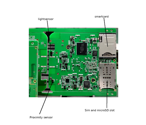
If you are right about light / proximity sensor, then it’s clear that this side goes to the screen.
As said above, there is no need to ever remove the PCB under normal circumstances.
With this orientation, all 5 slots can be accessed easily.

Also note that only the kill switches are directly soldered to the PCB, but not the volume / power.
That should ease (dis)assembly.

2 Likes

What I don‘t understand is, so near to the Q3 delivery date, why someone of Purism does not publish the design ans schematics to end all this guessing here.

3 Likes

Well… just guessing more here but… if they got the first pcb last week there may/should be testing involved and things can change (which would effect timelines), so no point saying anything yet. For a good pr event, it’s only a week until change of month…
Besides, this way we feed ourselves and they don’t have to waste time dangling tidbits daily until real news :wink:

5 Likes

I made the images assuming the open from the back approach an guessed on that that these could be light and proximity sensors. But the resolution is just to low for me to see many more details here.
I don’t think open from the back is impossible with a one piece back and you are right that buttons on one side and a bottom on extra boards also makes it easier.

1 Like

Thanks for your explanations. My first thought was also to simply look for sensors like the proximity sensor to identify the front.
So I am pretty sure that your ‘other side’ is the front side sitting under the screen (holding only small parts to stay flat). But I am not sure If you identified the light sensor and the proximity sensors right. I think the proximity sensor is the part you call ‘light sensor’ and the the light sensor is sitting left to the part you call ‘proximity sensor’. The proximity sensor is usually elongated in shape because you have a photodiode and an led sitting next to each other in one case.
I did overlay the 3D-pics and the front side of the pcb in Inkscape and the openings in the glass-cover do match the pieces I refereed to as light sensor and proximity sensor.


BTW the 3D-Rendering of the case are missing more important details like the slots for sd-card, so I would not bet that It is made of one part only having this low quality pics.

3 Likes

Good points. I assigned the front sensors randomly as i had no idea how to distinguish them.
I still think the m.2 facing backward is more likely. But i went from „ohh yeah thats obvious“ to „oh there might be a another option which is plausible“. Especially things like the headphone jack and buttons being mixup in render from the day 16 video and the ccc talk. I expect the position to be fix since month because PCB layout is complex if the already need 10 layers. You just don‘t casually change the positions.
But i also notice that the renderings a much more early prototype like. Maybe they just gave us old versions to keep the final look more secret.

Just another idea. In the pic withe to m.2 dummy in there is enough space between the cards to fit a „cooler“ in which touches the metal back and could dissipate the heat.

imagehttps://forums.puri.sm/uploads/default/original/2X/b/b0bbdce1e738a5ae60da024e0f1f3579dd6f89c3.jpg

1 Like

I just figured it out: this is why there is so much space and why it’s so thick! :smiley:


… would be an interesting choice :slight_smile:

15 Likes

To seem more realistic there should be 18650 or CR123a lithium batteries, not ordinary Ni-MH AAA ones. I did not see Ni-MH in energy-hungry devices for a long time.

Sure, but it’s about compatibility and to be able to get power anywhere and can be changed by user. And AAAs work better as a joke because they fit more easily :wink: (edit: I was at one point trying to fit an 3LR12 in there but gave up…)

2 Likes

Yup, this is exactly what I thought I’d do.
Heat spreader touching the back case.
And if it is not the default, people will tinker it.
But as the Purism guys are pretty smart, I wouldn’t be surprised if this was the default :sunglasses:

2 Likes

In the talk a VM was announced to test the L5 software stack… What do I need on my laptop as host with FreeBSD to run this VM? Qemu? Is the guest in the VM armf or x86_64?

Here you can find more infoirmation.

It’s qemu and x86_64

1 Like

Guru has a point. This is hardware you guys are talking about in Q3. I don’t think they’re going to change anything in this board at this point. It would be a great opportunity por Purism to write an update in “News & Events” explaining things about this board so people get it right. If this info was secret data it should not be accesible to anyone outside Purism. It seems to be important for many here so why not write a post about it?

1 Like