I’m looking for information about the built-in RAM and MMC. I didn’t find any information, just a little bit of information that it might be Toshiba MMCs. So, unscrew the phone
At some point I lost my courage and I stopped, but I wanted to share the steps up to then - including photos.
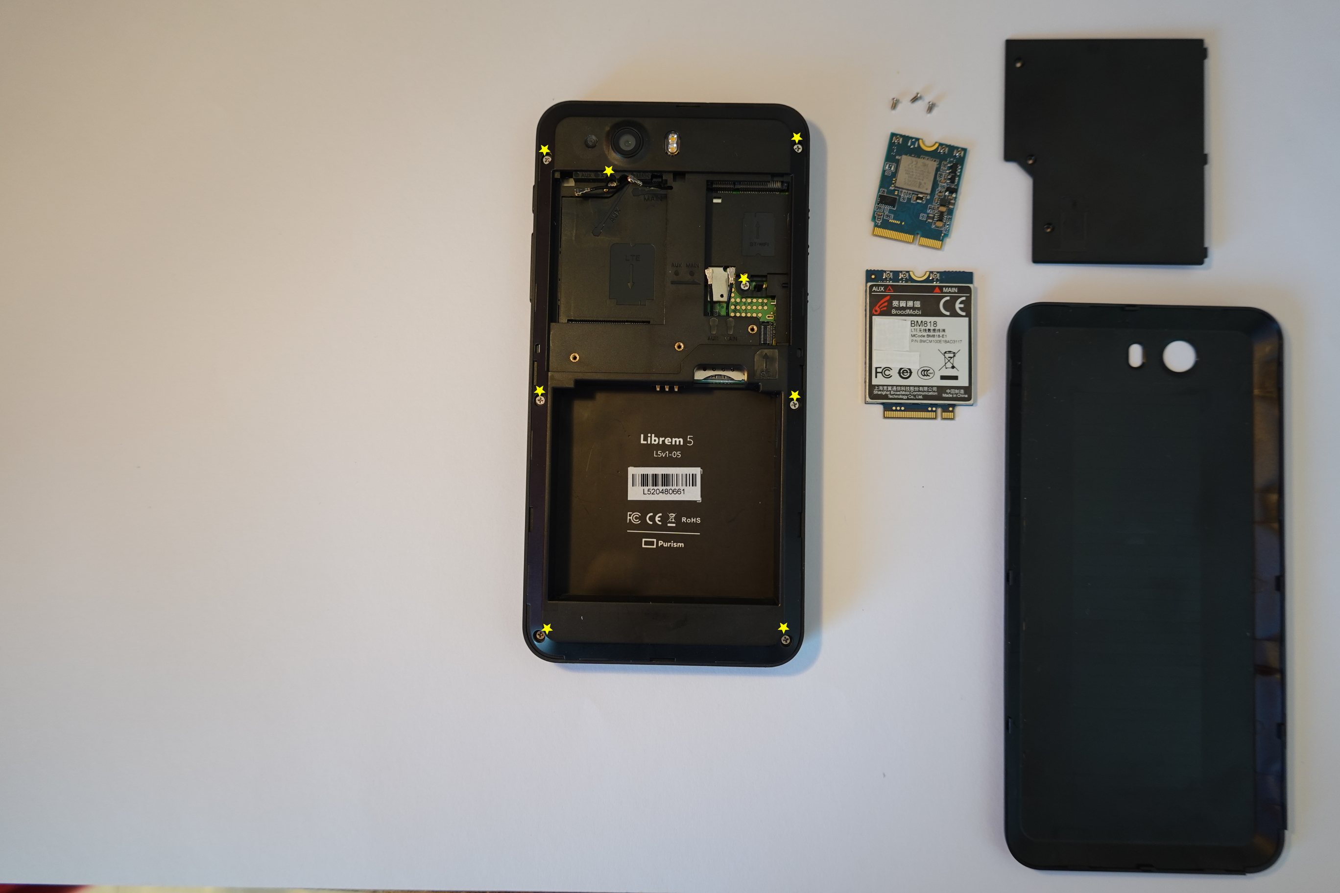
Yellow asterisks are the screws
Blue asterisks are “brackets”
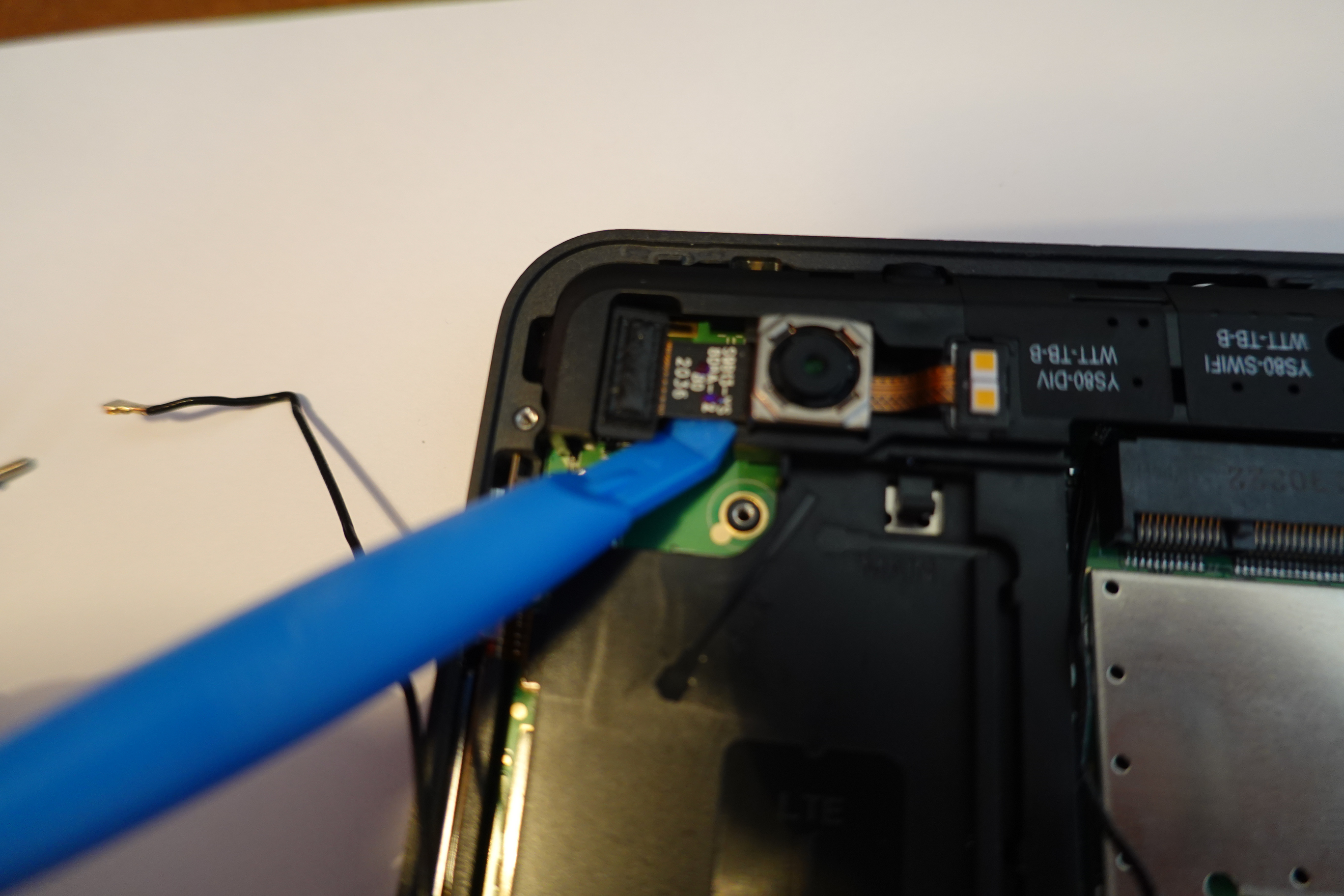
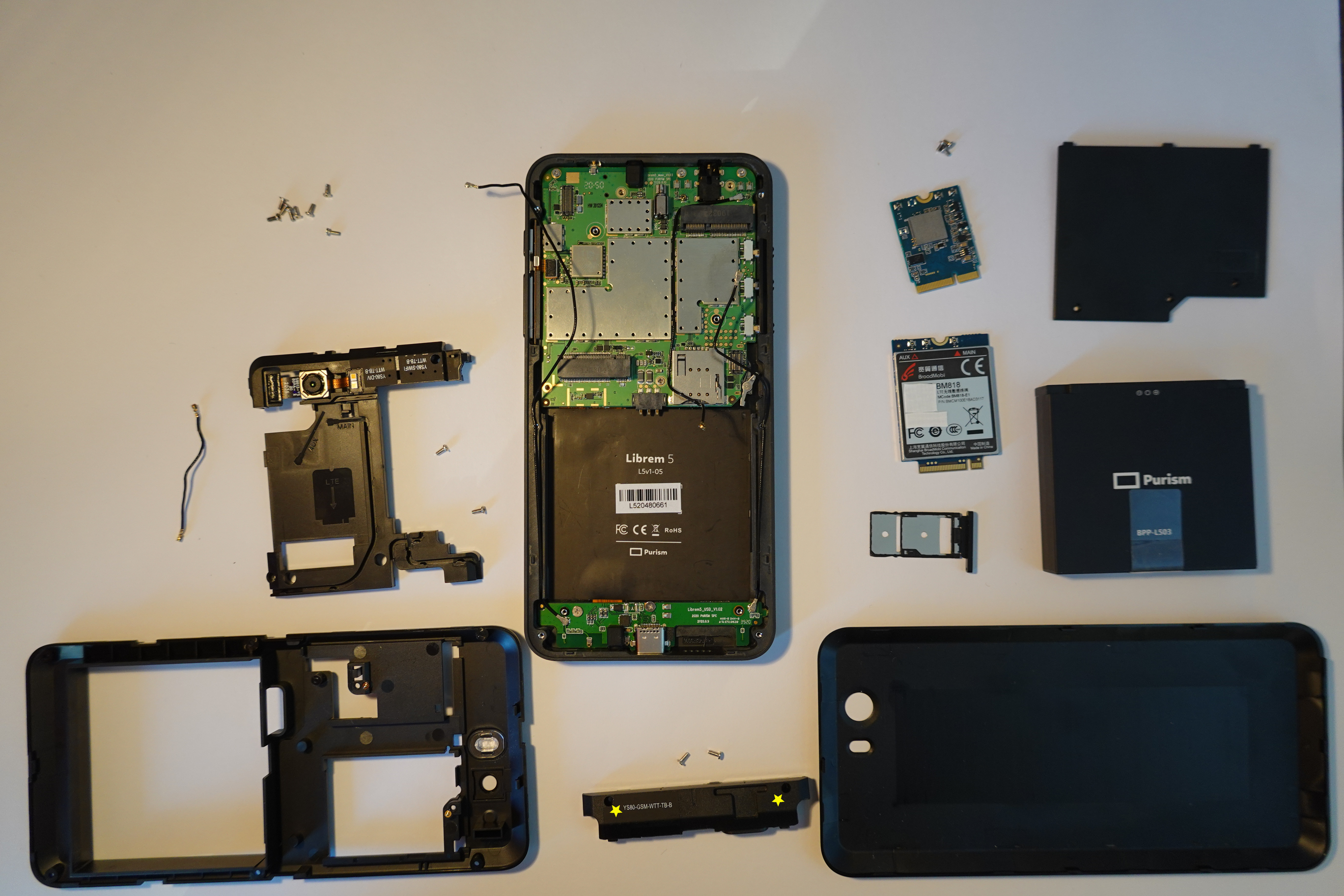
On the second picture you can see that a scribe is attached under the camera. On the third picture you can see how you have to loosen the cable from the camera, then you can loosen the screw (picture 4). On picture 5 you can see how I press the clamp outwards with a screwdriver in order to be able to finally loosen the whole plastic part.
I hope someone has more courage and can tell something about the built-in chips and post photos
@execrable, A couple months ago, I created a component list at:
I looked up all the manufacturers and included links to the web sites of all the components that I could find in the schematics.
It would be really helpful if someone would take high resolution photos of both sides of the two PCBs, so we can verify the parts and identify the location of each chip on the boards. The photos that Purism has released of the Dogwood PCBs are not high enough resolution and the lighting and camera focus is bad, so you can’t really identify anything. It looks like Purism has added heat spreaders on top of many of the important chips in Evergreen, but I still would like to see good photos if anyone is willing to take them. Just remember to replace the thermal paste after taking out the main PCB to take photos.
X-rays would also be awesome if anyone has access to an x-ray machine.


 to late
