If I add material to this picture to create two Battery Houses where one is rotated the same as the internal battery and one is flipped 180 degrees so that its positive and negative metal leads are touching in the same place, if I were to 3D print this Big Battery House backplate and then add small metal wires between the leads on these batteries and the internal area where the internal battery connects to the Librem 5, does the third pin do something in a way that would drive the Librem 5 haywire if attempting this or would something like this hypothetically use the batteries in parallel so that a Librem 5 could be used with triple battery capacity?
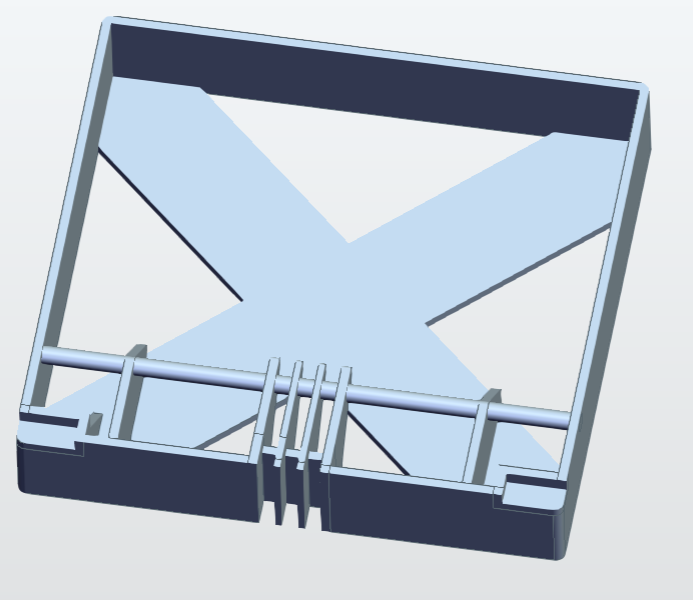
Edit: The tinkercad thing from Autodesk didn’t seem too good. I got going with Freecad and made some good progress once I figured out some of the buttons. I think I’m getting close to something that should be mathematically viable with the measurements but I’m coming to realize that it’s going to need a backplate-for-the-backplate:
One battery is the same as the original battery in orientation, and the other is flipped so that its positive and negatives line up in the same orientation as the other batteries. My thought is that for starters the Big Battery House can be a storage unit for spares while traveling, but I wanted to design it to leave open the possibility of wiring all three batteries in parallel with a small wire later if that’s even possible.
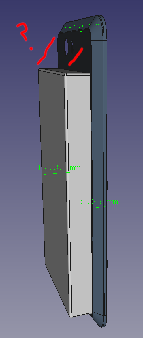
But this configuration introduces the problem that the “same orientation” lower battery will have his tape-to-pull-for-removal oriented the wrong way so that it gets stuck inside the Big Battery House. To help with this, I think I will cut some holes in the back maybe with a logo that allows the user to push through the hole on that battery. They say measure twice cut once, so I will probably do more work on this later in the week before trying to send it to a 3D print place.
Another thought: Will this be super unwieldy and need a more slanted edge??
I would not advise connecting 2 batteries in parallel like you suggest. Any differences in voltage and charging rates could potentially cause a problem as you’d have a voltage difference between them. This is not a good idea.
I was also thinking a catastrophic structural error in the housing could bring the two batteries together and short them, causing excessive heat or fire.
I was a little concerned about that too. However it seems that the terminals on the battery are ever so slightly recessed. So it may be that such shorting cannot in fact occur. It is certainly something that should be considered carefully.
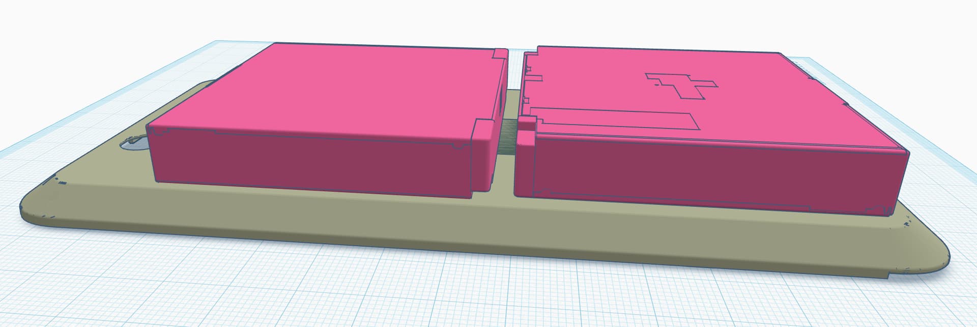
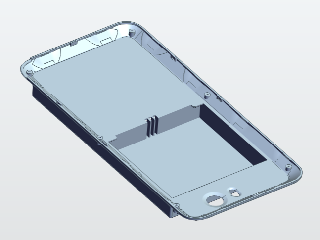
External backplate expanded to store two additional batteries
3 slot gap created between those two batteries allowing a wire to reach both of them hopefully
The two batteries are both held in place by the same mechanism as the original Librem 5 battery, namely two tabs at the top and the tape to pull the battery outward from where it sits
As a result of the above, coupled with the desire to put all “positive” terminals and all “negative” terminals together in one place for easy wiring, it is thus the case that one of the batteries loads from the inside and the other loads externally
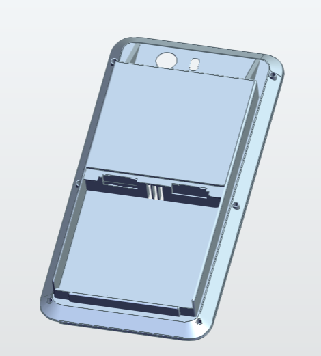
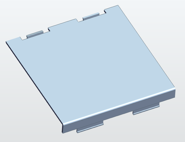
The externally loaded battery has a removable door with a design inspired by my GameBoy in the hopes that it will clip on and off more readily in case it’s ever useful to swap the “outer” battery
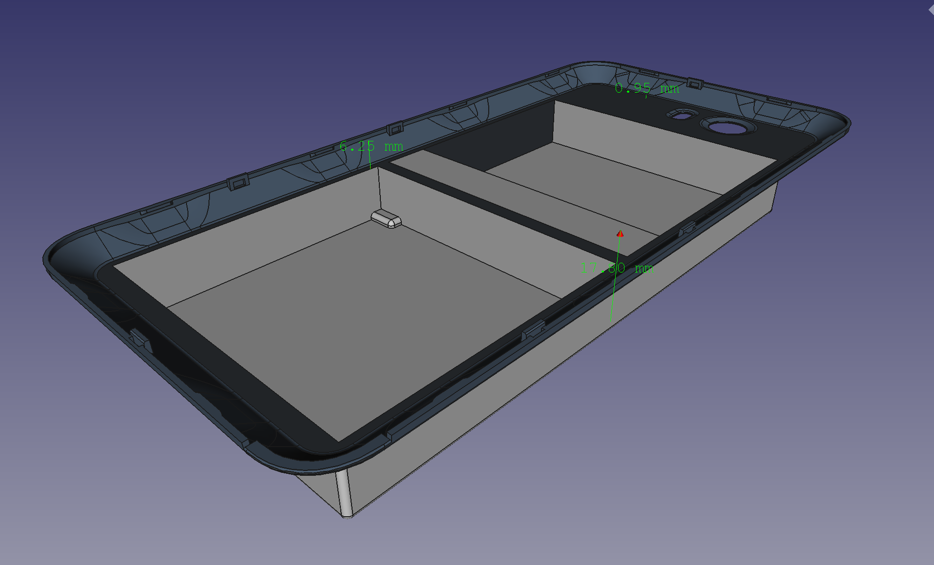
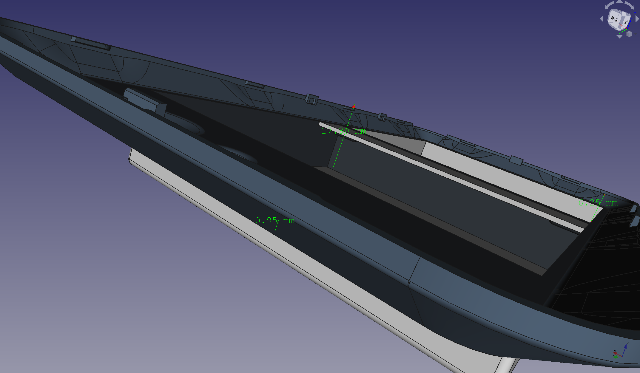
If desired, there is a space to screw the Big Battery House into the Librem 5 itself using longer screws and the pre-existing screw holes on the chassis, so that if the 3D print does not fit perfectly we’ll screw it in
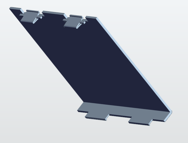
As well as the clippable "GameBoy” door on the back, there is a third component that serves as a spacer which can replace the interior primary battery of the Librem 5 and hopefully leave room for wiring around it and up to the 3 slots for the two exterior batteries, in part because:
They do not align their terminals exactly to the location of the original Librem 5 battery, and need about 8 millimeters of a wire to bridge the gap and wire them in
Fitting an extremely flat or thin wire between the internal battery and its terminals to allow two more to wire in might be wishful thinking, so it may be easier to have a 2 battery solution instead of a 3 battery solution
I’m hopeful that by throwing the kitchen sink of ideas at this project, even if some parts of the resulting design fail perhaps enough will work that it will result in a useful product.
Edit:
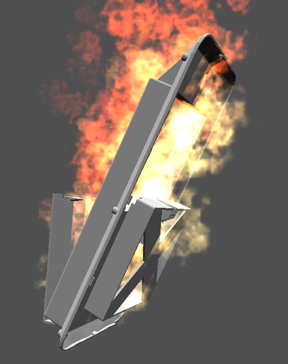
Was able to render the complete assembly and how this is predicted to look. Image shown below:
This shipment of 3D printed parts arrived, and I was able to assemble them together and boot the phone off of batteries in the back compartment that were loosely connected by some wires in the spacer component that I pushed into place with my hands. I had the wires floating around in some box of wires from an electrical engineering college course from a decade ago, and did not know if they were necessarily correct for the job. But I used them anyway, and tried to bend them into place on the device.
I found that when the interior battery on the Librem 5’s main compartment had been removed, I was able to still boot the device from the second battery above that compartment with the removable door, however the Librem 5 was refusing to boot with only the one battery below the camera inserted which would have presumably meant the loosely added wires were not quite touching that battery, or not until the second battery was added. [Because of this, I have also not confirmed or denied whether the second battery is able to join the circuit in parallel and trigger longer battery life.]
The batteries seemed to report strangely low charges in the range of 10%-20% by the time I finished fighting the wires into place, even though they had originally been fully charged to my knowledge when I started. Does that mean a bunch of shorting was happening?
It also seemed very difficult to shove a custom wire into place and have the battery boot off of this reliably, so one of the things I did was to wrap the wire around the springy metal connectors that usually touch the battery to hold it in place. After some testing, when I removed the battery house, this effort to wrap the wire tightly around the metal connectors resulted in one of the metal connectors ripping out of the Librem 5 and I have not been able to finely manipulate it to go back into the Librem 5 (for example if I wanted to change back to using only 1 battery) which seems highly concerning.
Edit:
No attempt was made to charge the phone while multiple batteries were connected via the shoddy wiring, even though a “shoddy wiring” boot has been proven to be possible and it showed strangely low charge on the battery which remained after removing the battery and testing them alone in a standard Librem 5 (suggesting that either shorting nuked the battery or else I started with batteries that were not as well charged up as I had expected).
Battery charge level will probably be horribly confused by what you have just done, requiring either a recalibration or a software change (without which it will just always be wrong) or both.
To be clear … there is no easy way for electronics (never mind about software) to determine the battery charge level. To make further progress on that specific issue would require
Why not keep the three standard Librem 5 batteries, while also building a PCB to add professional looking work to integrate all of the electronics and physical connections inside of the 3D printed back shell?
I would use a very thin piece of plastic to electrically disconnect the Librem 5 from its battery within its own compartment. Each side of the separator would have an independent conductor that connects to the PCB, so that the battery connection to the phone can be restored electronically, from the PCB. Use surface mount components to put separate battery management system circuitry on each of the three Librem 5 batteries. But connect a power bus from all three batteries somewhat in parallel, to the Librem 5. I would also put a higher current barrel connector or another USB-C connector on the outside of the case to facilitate faster charging at a higher current than the Librem 5’s USB-C and respective charging system can provide. In this case, a Laptop or Tablet charger might be needed to charge all of the batteries at once.
If you put the added circuitry along side or above or below the two external batteries on the PCB, there should be plenty of room inside of the case for the added electronics on the PCB. You will only lose one-16th of an inch or so, to the thickness of the PCB. But in return you will gain a double-sided platform to both reach in to the battery cavity on the phone, and also upon which to mount the other two batteries and electronics. The solder mask on the PCB will reliably insulate the thinker battery power busses from the from everything else, while having almost zero thickness (for all practical purposes), inside of the case.
You can download and use KiCad (it’s free) to design the schematic and linked PCB files and generate the Gerber files from which to order the printed circuit boards. You can take physical measurements to make the PCB fit like a glove in to the 3D printed case. I can help you with the electrical design if you’re interested. The electrical design should be super easy to do if the right BMS chips can be found. Otherwise, some home-done R&D might be required to get everything right.
Another advantage of putting a separate external USB-C connector to the case for only battery charging is that convergence problems might be resolved that way. The USB port on the phone could be used strictly for keyboard, mouse, and monitor, while the batteries are charged from a separate power connection that does not require use of the Librem 5’s only USB port.
Yes please! I am interested but do not really have electrical engineering experience.
Here are download links for the CAD files used in my first draft 3D print. The measurements seem to fit and I can screw this thing into my Librem 5 and close the detachable door over the outer battery (although its proportions could be slightly better) but this thing isn’t wired properly to make all the batteries work:
Thanks Dlonk, I’ll have to find a program to be able to open these files that you sent. Let me know if there is a good free one out there and where to get it. The only CAD programs that I am familiar with are used to generate schematics and layout files and turning those schematics and layout files into the evelectronic files that a PCB fabrication house needs to build circuit boards. I am interested in getting these three batteries to all work together in this enclosure as I can use this myself also. If there is not one-sixteenth of an inch or so of spare room in the enclosure thickness, the design of the enclosure might need to be increased in thickness a small amount to accommodate the PCB thickness. If the idea catches on, we could order PCBs in a batch for anyone who wants one. A two-layer PCB the size and shape of the Librem 5 would only cost around $20 each on the high end and $10 each on the low end, based on a lower price at higher volumes of only five to ten boards. The cost of components should not be much either. But finding custom components can be difficult.
This coming weekend, I’ll start looking for the battery management chips online. I can also start a new KiCad project and start taking physical measurements on my Librem 5 to figure out the exact required PCB size and shape, and to enter those physical dimensions in to the layout palate in KiCad.
I can put out the Schematic and PCB files to this forum so that anyone who wants to, can open and examine those files and build upon them. The Kicad software is free and the learning curve is not very steep. But just to open and examine the schematic and pcb files, the KiCad program has to be installed.
They were made with FreeCAD on my Librem 14, which was installed on PureOS using the standard sudo apt install freecad of the PureOS distribution, so as far as I know it should be entirely free software since PureOS is endorsed by the FSF.
For me that was not necessary, I was able to measure all the dimensions of the Librem 5 components virtually using the files provided by Purism.
Below is a video of how I attempted to almost wire the device, and even managed to boot it one way in a manner similar to this, but in the process I damaged one of the small 3 connectors that attach to the battery. Having some sort of PCB solution like you’re saying might be really nice.
But I think you can see from this video that for me, the measurements used to create my FreeCAD files came out very accurate – all while measuring the Librem 5 components virtually rather than looking at my actual physical device.
[Video redacted, it may reappear later in an updated form]
(Side thought: am I exposing myself to some sort of risk by including a video with the S/N here?)
The video was quite slow but I hoped that it would make visible how you can see the batteries in my first prototype do fit, and many aspects of the shape are good, but when I try to wire it connecting the positive terminals of the batteries in one column and the negative terminals of the batteries in the other column, wires that I tried thus far were being put into place by hand and ended up not quite working. There was one instance where the wires happened to be in place for a time, such that I could boot the Librem 5 off of one of the two batteries there while the normal “battery compartment” had the spacer shown in the video in it – with the wires – and not a battery in that normal compartment. But I’m not convinced it was using both of the batteries and I haven’t gotten it to do that again because although I have these 3 columns for wiring, I don’t have properly shaped wires that would always connect to the terminals while also being present in the correct area.