Case for Librem 5?

I’m using this fitBag (the 3rd item in this table https://source.puri.sm/Librem5/community-wiki/-/wikis/Tested%20Accessories#cases) and I was since the beginning afraid that the L5 could fall down while pulling it out of the bag or putting it in again. And yesterday it happened. I was able to put my shoe on the point where it would hit the ground and so no damage happened. As a rule of thump I will do it in the future only above a table or above my lap.

A good case should protect the display and the four corners of the L5 and should allow that the heat goes out too.

How big a consideration would heat dissipation be? If the case covered the back, should it have something like a grid of little holes or something to let heat out?

I think more important are holes on the side because the heat gets delivered through the metallic side frames of the L5. This must be tested, though.

1 Like

So here I am again for a 3D case feedback !

I decided to take this STL file proposed in the gitlab and not having a 3D printer, I sent it to a professional who uses MJF injection technology, and I chose TPU for its flexibility and at the same time robustness properties.

The shell alone:

the 3D printing shell made in MJF/TPU is very impressive: no streaks, no burrs, the holes are respected and the angles too. As if it came from a factory. The thickness of the walls gives an impression of great strength, and the rough texture gives a feeling of grip that I particularly appreciate.

Assembly of the shell on the smartphone:

Dimensions:
the dimensions are good but not perfect in my opinion. The holes on the sides are such that there is a slight looseness and therefore it does not fit the smartphone 100%. By analogy, to give an idea, let’s say it fits horizontally at 95% without the shell coming off easily. Buttons and switches remain accessible even if you have to make a small effort to reach them (the author of the STL file played on the relief with “chamfers” to facilitate access to the buttons, it’s a good idea), and the USB and audio jack connectors are wide enough to connect cables without being blocked by the shell.

Robustness:
we are not disappointed, the person who made the STL file had the very good idea to cover the relief of the 2.5D screen, which is the most critical part of the device. On several fall scenarios, the shell might protects the smartphone well but there may be scenarios where the screen can break (eg: violently flat, a large part of the shock could be absorbed by the shell, but it may be that the deformation causes a floor-screen contact) and that’s where a glass screen protector can help to absorb the rest of the shock.

Aesthetics:
this is where the real problem lies. I already noticed it a while ago: the corners are almost rectangular, a lot of holes are too, and the thickness makes it look too rectangular and massive in hand / on the table. With this case, we move away from the shape of a smartphone, especially when you stick the device on your cheek to call.

Conclusion:

There are definitely areas of improvement for this STL file. I have in mind a few things to improve:

  1. round the corners at best to avoid the massive rectangular effect
  2. round all the holes to have a more welcoming design
  3. except for the part surrounding the 2.5D screen, reduce the thickness to the strict minimum (1.5mm at the back, 1mm everywhere else) to gain in thinness
  4. reduce the height (I mean vertically distance jack audio <-> USB type-C) by 1mm
  5. reduce the width (horizontal distance, I mean distance kill switches <-> vol buttons) of the part of the shell close to the screen (the bottom part is OK) by 3 mm to make the shell more flat against the smartphone
  6. correct the position of the speaker holes (at the bottom) and the camera holes on the back because they are not aligned:
  • speakers : center toward the USB type-C by 1mm for each hole
  • camera (point of view seeing the back of the smartphone) : correct the hole to 1mm to the right, and 1.5mm to the bottom.
  • flash LED hole: correct the hole to 1.5mm to the bottom, and change the shape from a rugby ball to a rounded rectangle.
  1. reduce the height of the speakers holes by 3mm
  2. make rounded chamfers for each hole for aesthetics

If someone knows an open-source and user-friendly (I am a totally beginner) software to help me to modify this STL file, please do not hesitate. If you are afraid that it will take me years to get the software in hand, you can also start making STL updates following my comments!

6 Likes

Would you mind posting a picture or two?

4 Likes

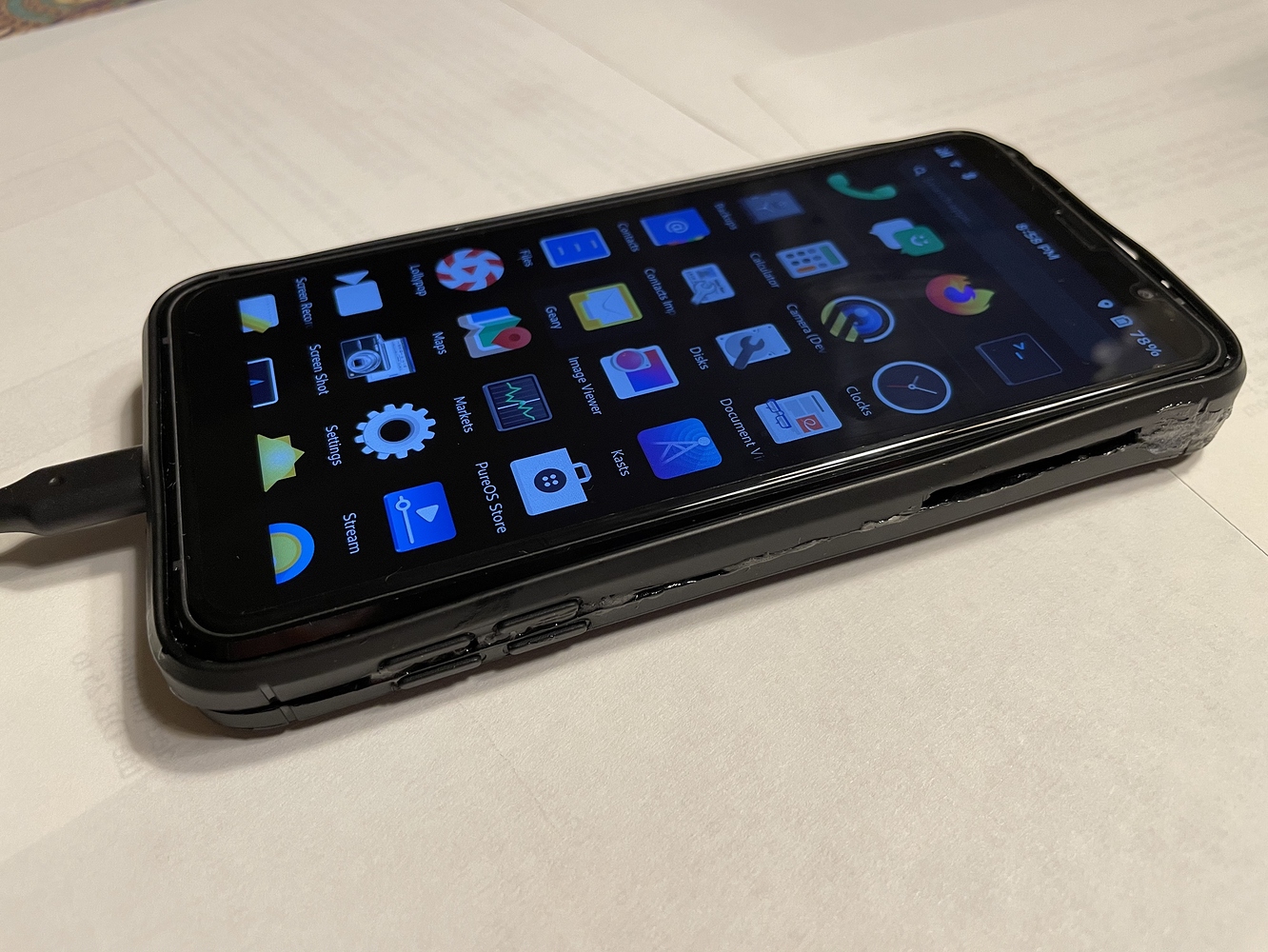
Here are the photos of the shell showing an overview, and what to improve.

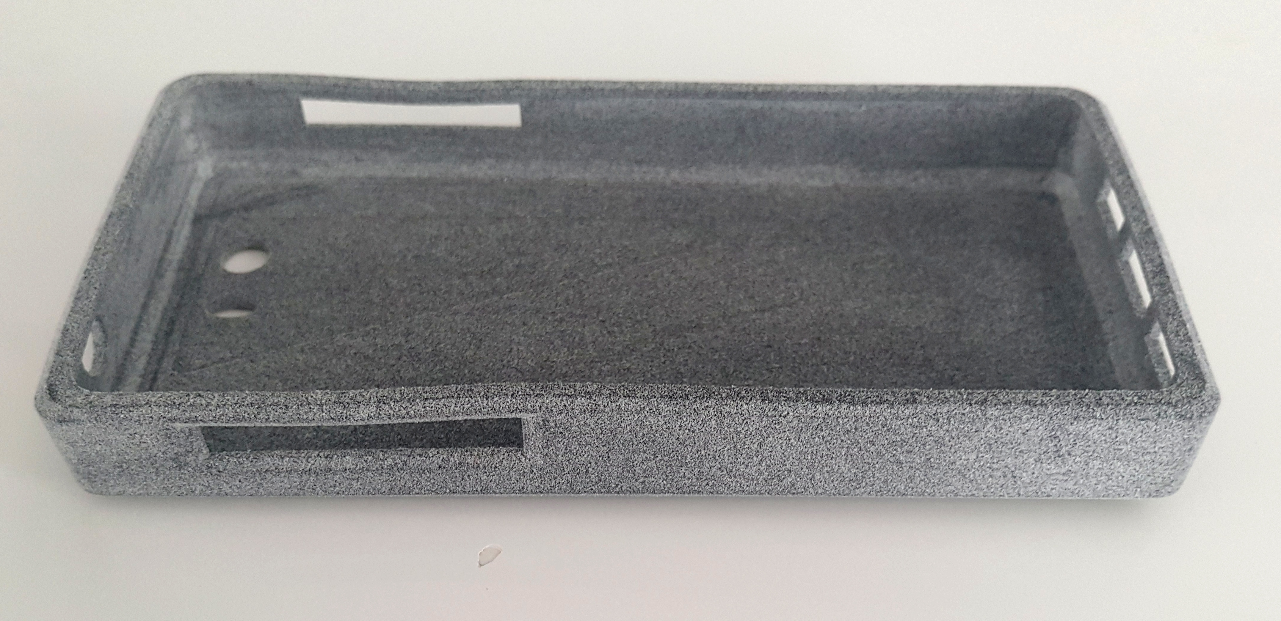
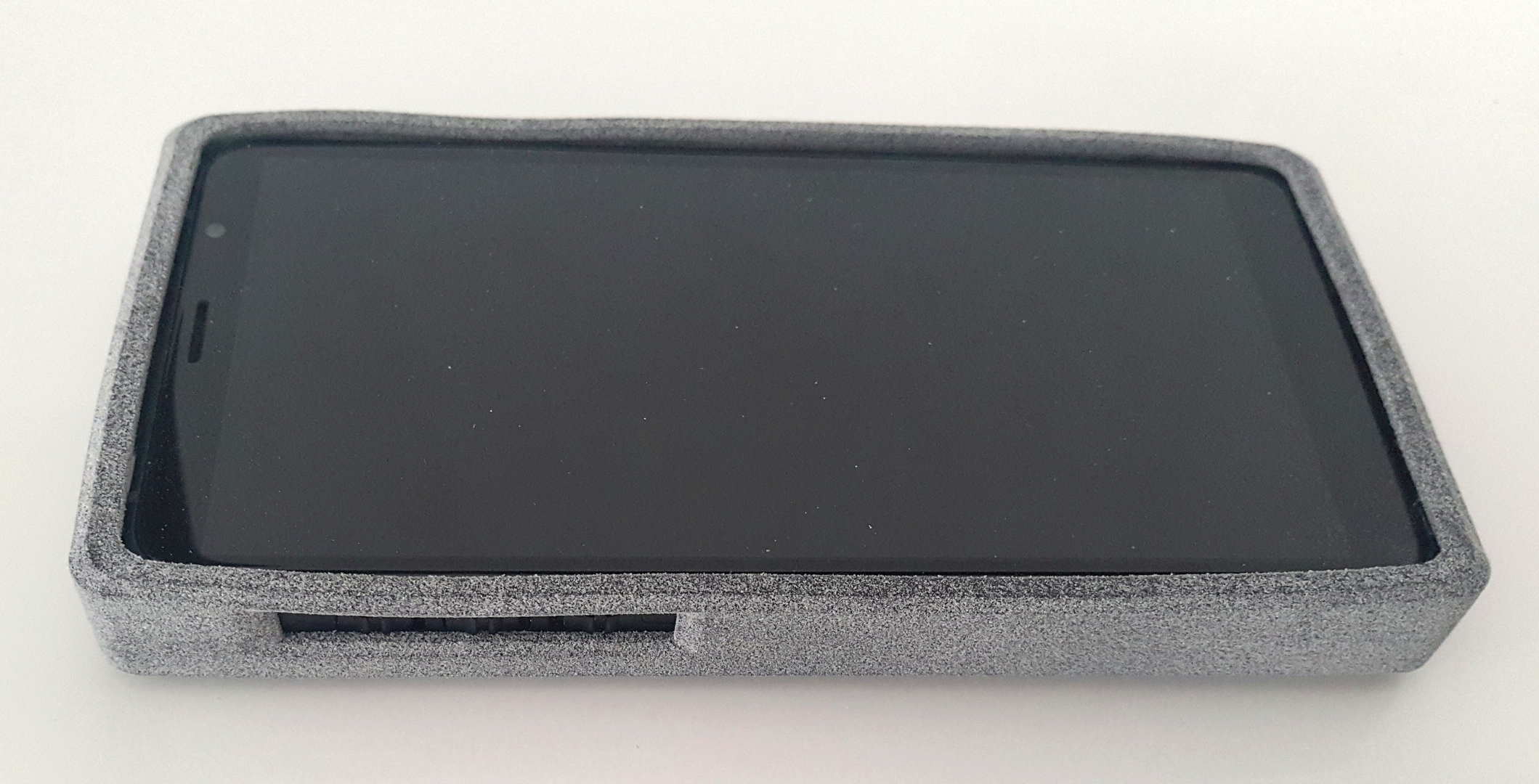
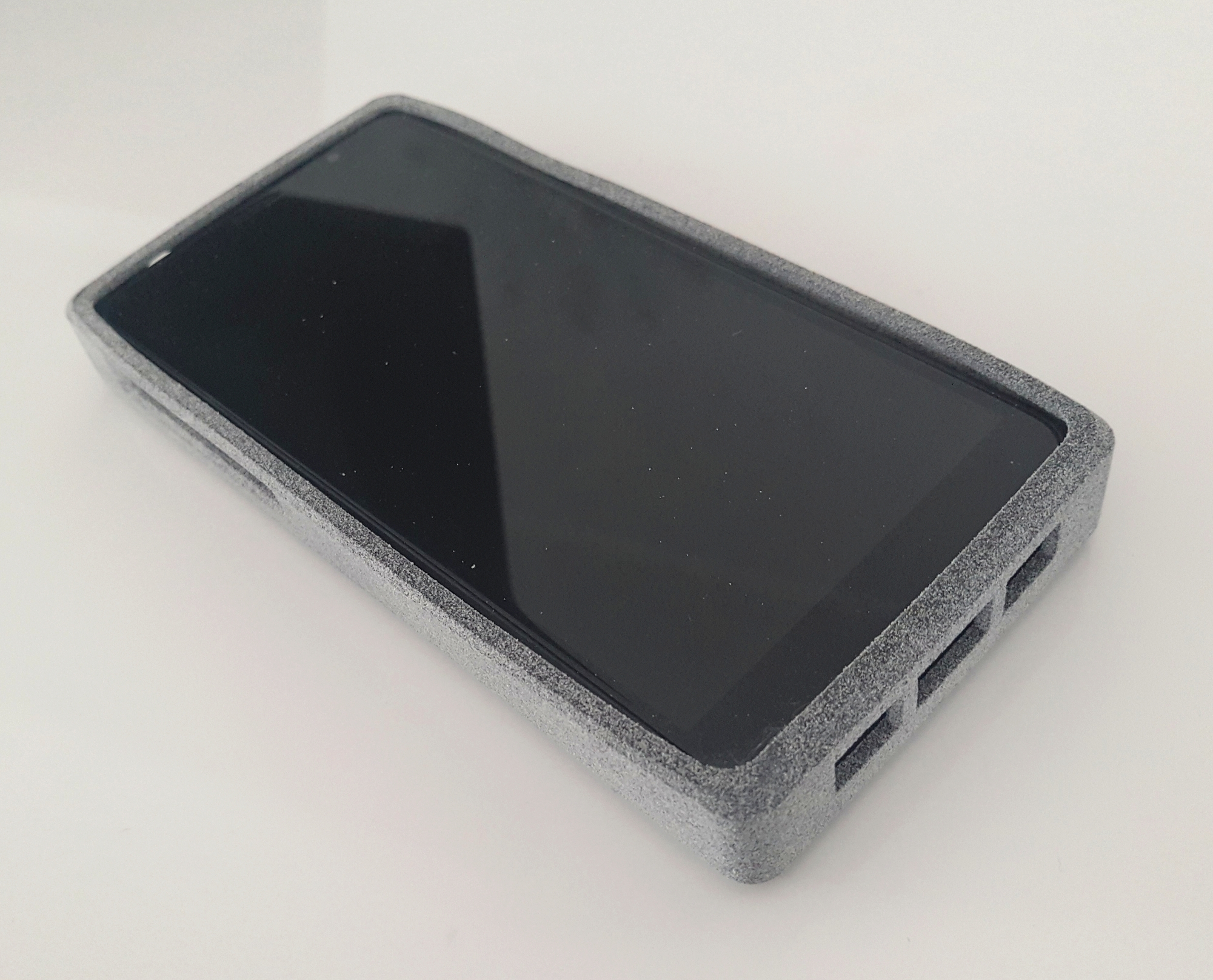
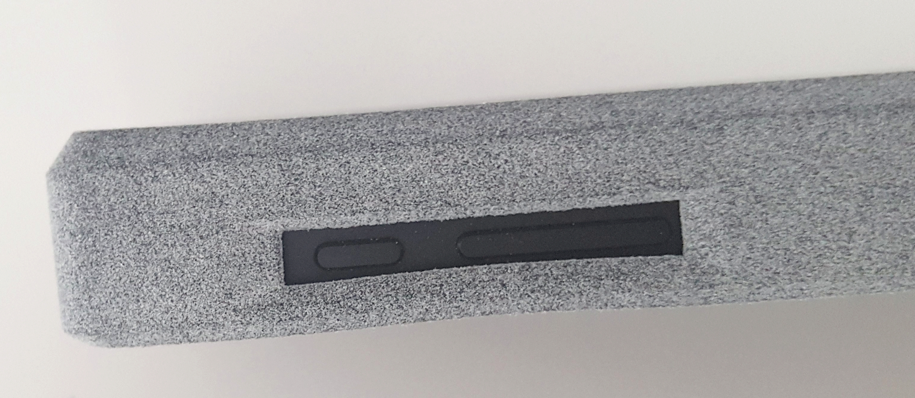
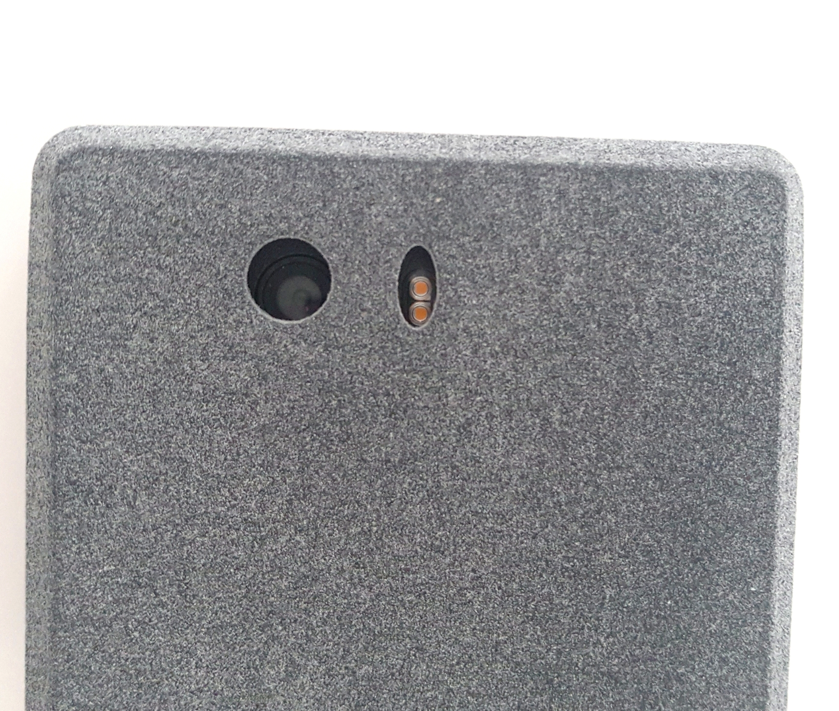
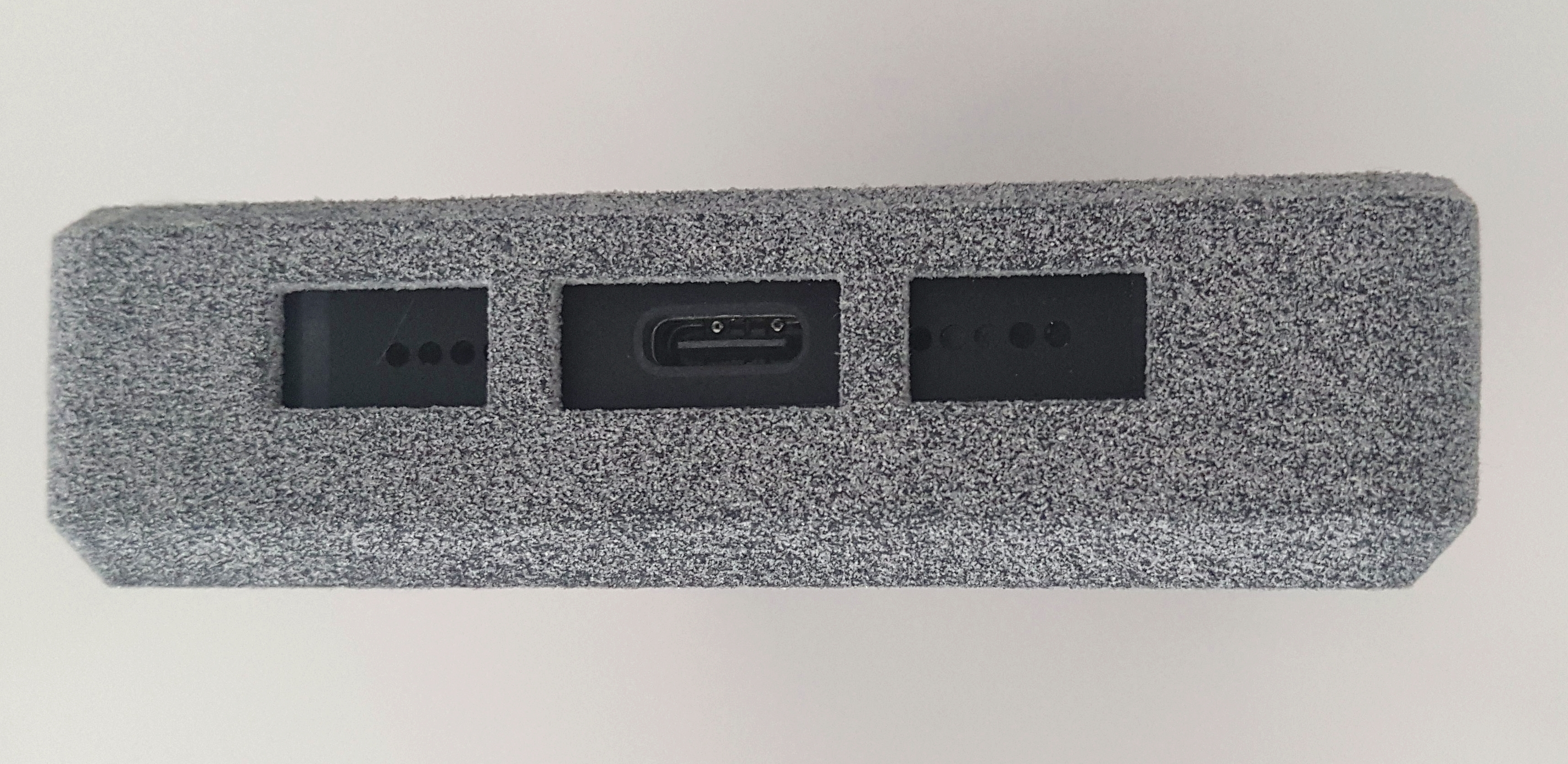
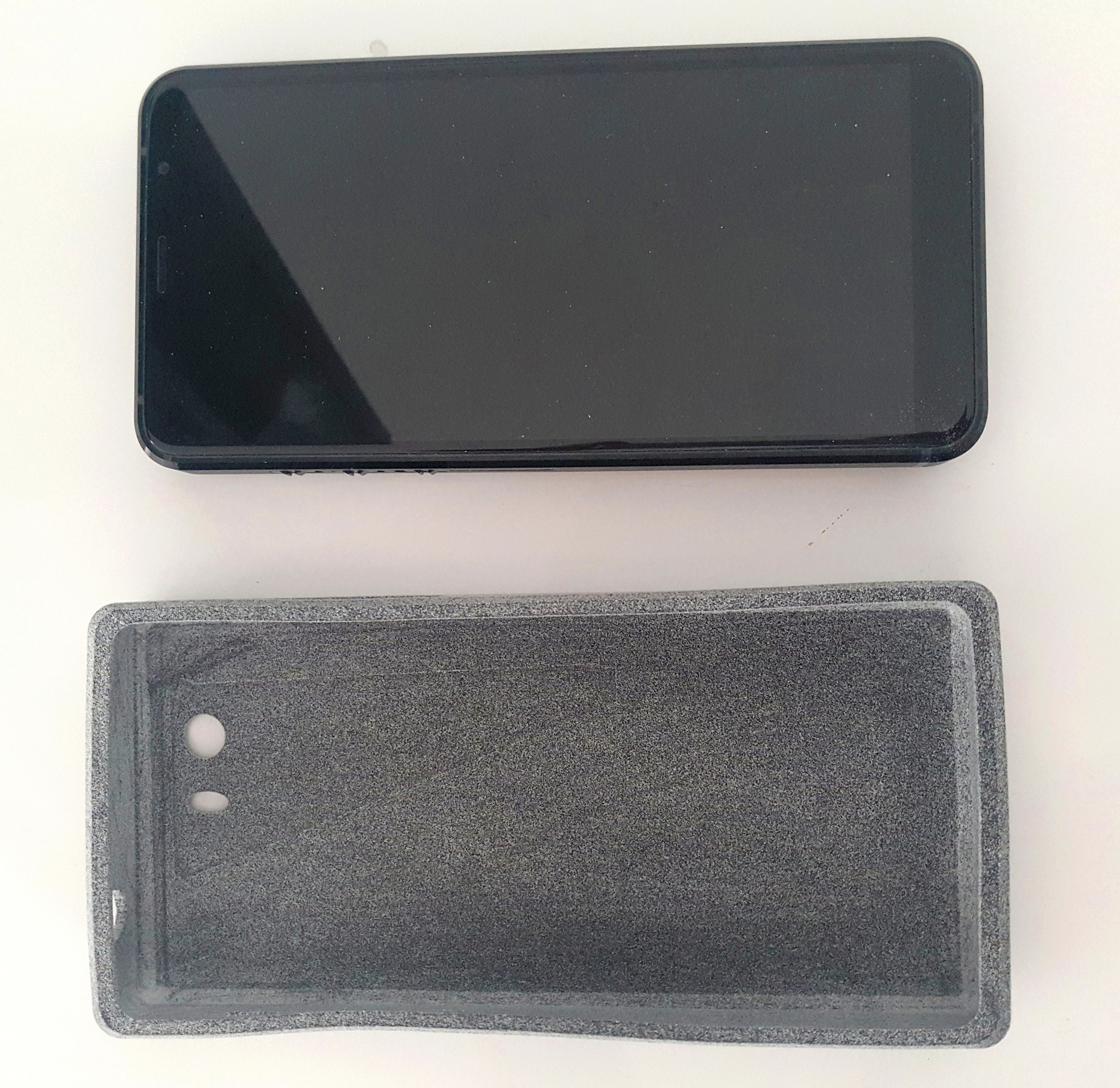
As you can see, the square shell increases the thickness. Comparing with the DIY shell of @Zimmy , it seems that I have something more imposing, and less rounded with this 3D shell :

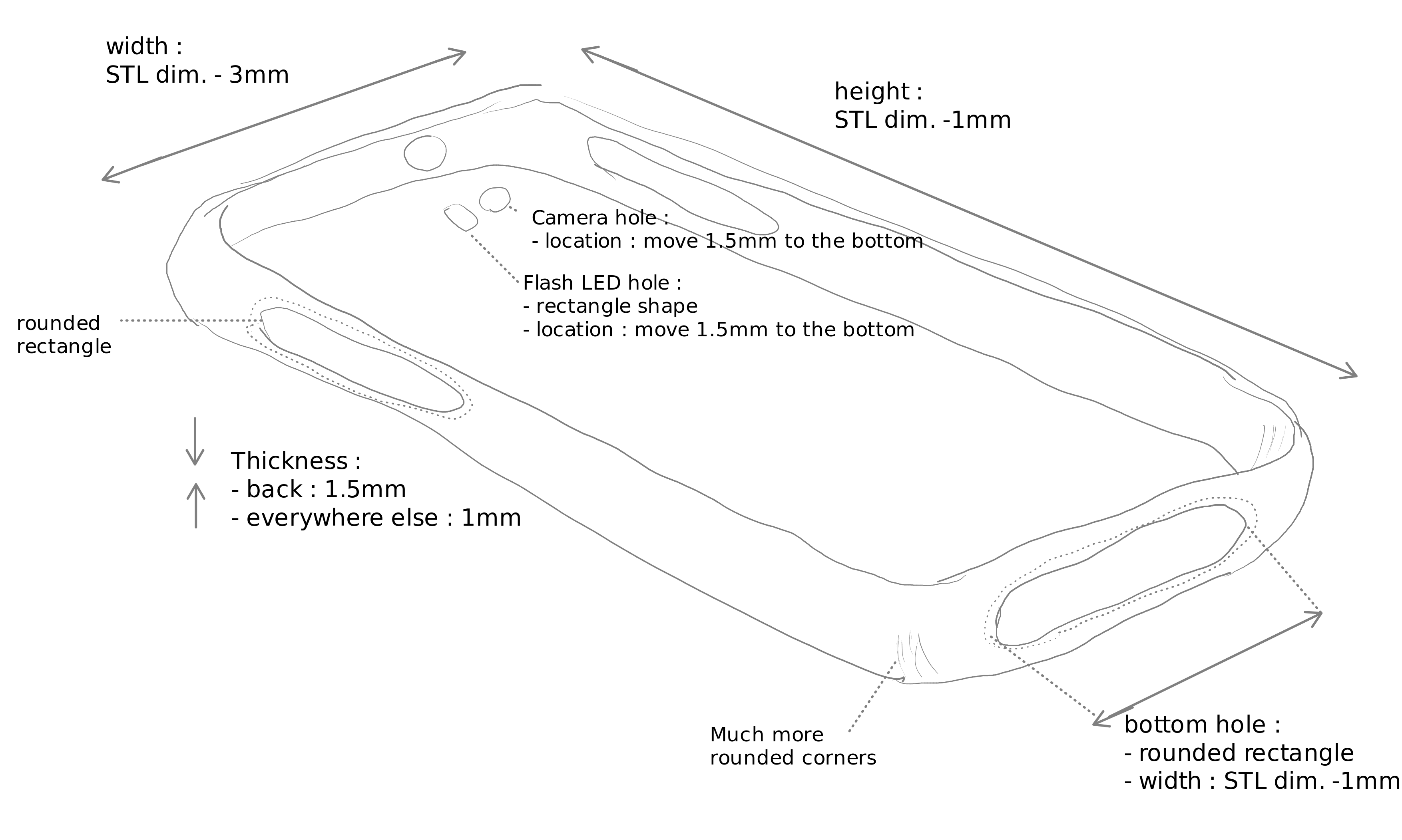
I tried 3D rendering with TinkerCAD (open to beginners) but nothing works: I can’t easily modify the original STL file due to lack of skills, so I made a sketch of what I want to correct on the original STL file, based on my previous feedback :

Question :
Does anyone have the skills and time to modify the original STL file according to my recommendations? That would be really great, and we could add it to the Purism git webpage !

10 Likes

Does the hole over the volume and power buttons need to be widened vertically a bit? It seems narrow for a fingertip to effectively use the volume button. But if it’s easy as is, then disregard.

I also wonder if the camera hole needs to be enlarged to prevent the case from ruining photos…?

Volume & Power buttons + kill switches are reachable with the case, but you have to make an effort (however it is not annoying at all). Maybe as you said, we can increase the volume & power hole for about 0.5 to 1mm maximum.

Yes exactly. On my sketch, you can see that I ask to move down the camera + flash LED holes to 1.5mm because they are not aligned with the hardware. Also, I think we can change the current “rugby” shaped hole of the flash LED into a more rounded rectangle, more harmonious shape.

I think it would be very cool if somebody having a 3D printer with flexible TPU filament could modify the original STL, test and try the new case because the current one has qualities but on the other side, it can be improve because it is very thick and “squared” with a few misalignment.
I think @Zimmy case shape is the objective to reach.

2 Likes

As a concept, stretch-to-fit cases like these may be possible: https://www.amazon.com/Universal-Elastic-Silicone-R0172WW-R0170WW/dp/B0863QDSRT and https://www.amazon.com/Universal-Lanyard-Silicone-Compatible-Smartphones/dp/B082TQ42Y8/
One could even DIY one with a couple of stretchy bands.

2 Likes

By far this can be the best solution for those who want to have something ready to use and who like this design

I was just looking at this, does anyone know if thickness can be supported by these?

I’m looking for good bumper case

For Librem 5 Fir, Purism might want to ask the people from MIT to collaborate on developing the case and screen :wink:

5 Likes

The new polymer sounds amazing, but using experimental materials is not Purism’s goal, and that kind of expensive R&D is best left for companies like Samsung which have deep pockets and armies of engineers to perfect it. Rather than something exotic, most people will be content with a simple TPU case that doesn’t require much investment on Purism’s part and can be created quickly.

1 Like

I wasn’t expecting Purism to be included in such an endeavor at all hence the smiley

1 Like

Hello, I am discussing with people in purism git. Now, I am waiting for instructions about how to modify STL files in OpenSCAD :

So far I feel I am almost alone in this adventure, any help would be very appreciated !

3 Likes

Good job! That’s a nice looking case!

1 Like

I can help.
What is the starting file? I see that there are many .stl under the case folder.

1 Like

Forget it, I’ve just found it few posts above

Thank you, I give you a big heart for this !

To summarize, here is the starting STL file :

And here is a summary of the proposed instructions :

In the instructions diagram, I made a mistake. It says :

Thickness :

  • back : 1.5mm
  • everywhere else : 1mm

while the correct modifications are :

Thickness:

  • back : original STL dimensions minus 1.5mm (unless we are already at 1.5mm, the idea being that the thickness at the back must be very thin)
  • everywhere else : original STL dimensions minus 1mm

If you see that it’s too time consuming, please forget it, I don’t want to burden anyone with hard work !

In any case, a huge thanks for your kind help.

1 Like